Glue dipping head for conductive glue coating

A technology of dipping the glue head and conductive glue, which is applied in the direction of coating and liquid coating on the surface, etc., can solve the problems of insufficient glue overflow around, chip pad short circuit, difficult production standards, etc., and improve the coating of conductive glue Quality, simple production procedures, and the effect of improving production efficiency

Inactive Publication Date: 2019-09-20
CHINA ELECTRONIS TECH INSTR CO LTD
View PDF6 Cites 0 Cited by
  • Summary
  • Abstract
  • Description
  • Claims
  • Application Information

AI Technical Summary

Problems solved by technology

At present, these two types of dipping heads have some deficiencies to varying degrees, especially in the high-density packaging of multi-chip components. The stability of dipping glue is good, but when dipping large-size chips, it needs to dip glue multiple times to complete the coating of conductive glue. The production efficiency is low and it is not suitable for large-scale production, and the automatic glue dipping program is complicated to write and difficult to debug; and Although the second type of special dipping head can be designed specifically for individual chips, it is more difficult to meet the conductive adhesive overflow effect required by the national standard, especially when multi-chip high-density packaging is prone to chip pad short circuit or surrounding The problem of insufficient glue overflow, and in order to maintain a stable coating amount of conductive glue, it is necessary to strictly monitor the height and viscosity of the conductive glue in the dipping tray. It is difficult to achieve high-quality production standards in this mode of operation

Method used


Image

  • Glue dipping head for conductive glue coating
  • Glue dipping head for conductive glue coating
  • Glue dipping head for conductive glue coating

Examples


Embodiment Construction

[0021] Attached below Figure 1-5 The technology will be further described with specific examples to help understand the content of the present invention.

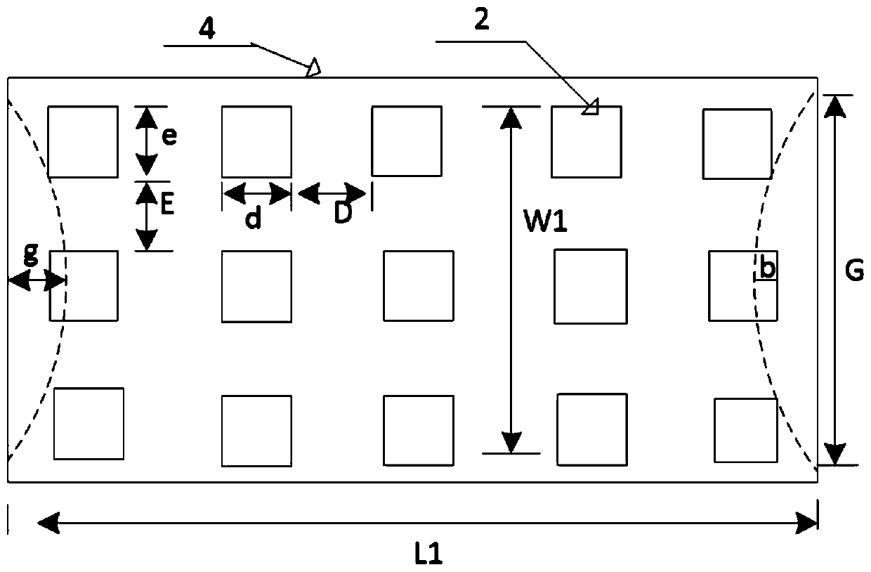
[0022] This technology focuses on multi-chip high-density packaging, and the dipped bumps are at least two rows and two columns. In this embodiment, three rows and five columns are used as an example:

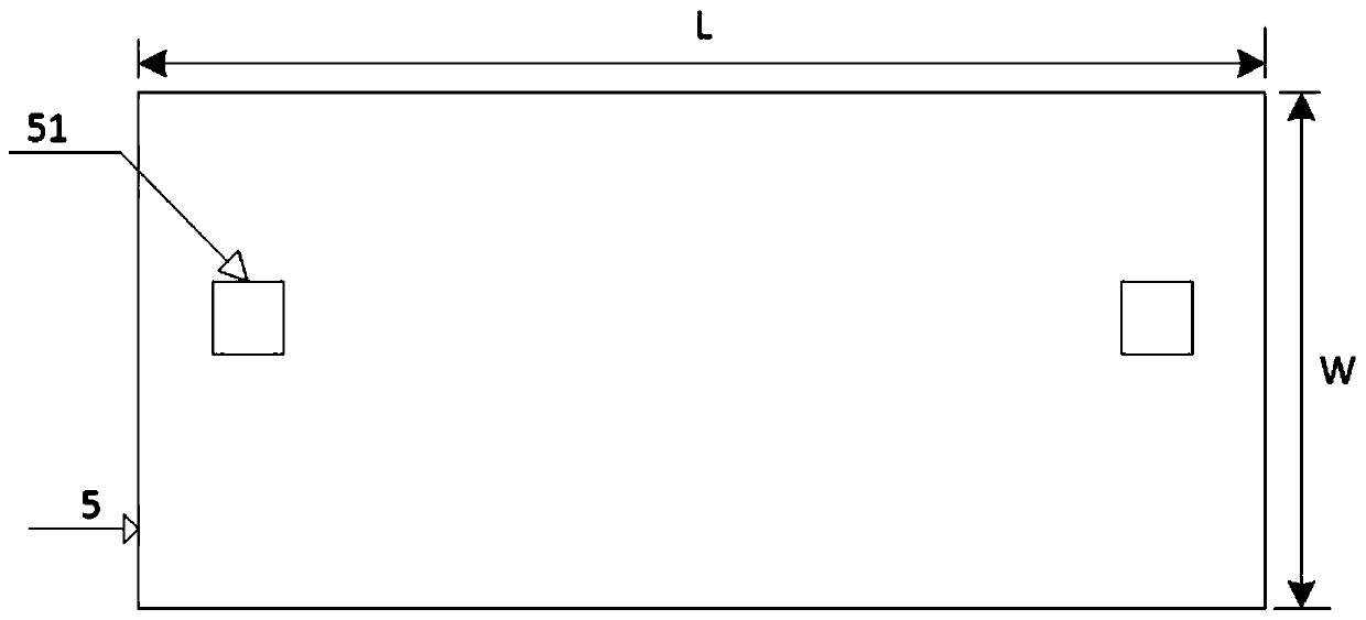
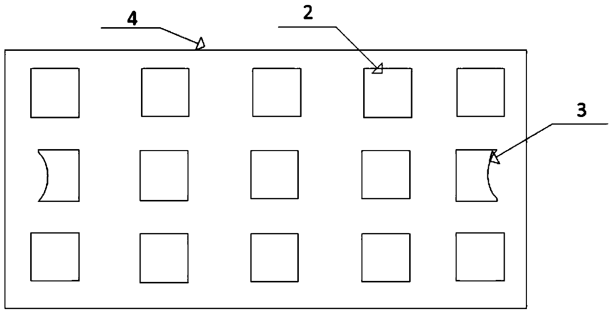
[0023] A dipping head for coating conductive adhesive, comprising a connecting shaft 1, a rotating body 6, a dipping head base 4, a dipping bump 2 and a dipping shrinkage bump 3, wherein the rotating body 6 is fixedly mounted on the connecting shaft 1, the bottom of the connecting shaft 1 is provided with a dipping head base 4, the dipping bump 2 and the dipping shrinkage bump 3 are arranged on the dipping head base 4, the dipping bump 2 and the dipping shrinkage bump 3 Arranged in a matrix, the dipping contraction bumps 3 are located on the outermost side of the dipping head base 4 and correspond to the positions of the c...


PUM


Abstract

The invention discloses a glue dipping head for conductive glue coating. The glue dipping head comprises a connecting shaft, a rotating body, a glue dipping head base, glue dipping salient points and glue dipping shrinkage salient points, wherein the rotating body is fixedly arranged on the connecting shaft; the glue dipping head base is arranged at the bottom of the connecting shaft; the glue dipping salient points and the glue dipping shrinkage salient points are arranged on the glue dipping head base in matrix arrangement; and the glue dipping shrinkage salient points are positioned on the outermost side of the glue dipping head base. The glue dipping head has the advantages that the space layout of the glue dipping salient points is optimized, and the size and structure of the glue dipping salient points of a bonding pad of a chip are optimally designed, so that the ideal condition that effective overflow of the conductive glue on non-bonding pad parts of the chip and proper overflow of the conductive glue on the bonding pad parts of the chip is achieved; and according to the glue dipping head, the production efficiency and the quality of the conductive glue coating are improved, the viscosity change of the conductive glue and the height of the conductive glue in a glue dipping disc are less affected, and the glue dipping head is beneficial to large-scale production.

Description

technical field [0001] The technology relates to a glue dipping head for coating conductive glue, which belongs to the field of machinery manufacturing equipment. Background technique [0002] In actual work, the dipping heads used for coating the conductive adhesive of the automatic placement machine can be roughly divided into two categories: one is the general-purpose dipping head with a miniature dot design, which can only be completed each time. A conductive adhesive coating with a dot structure requires a fully automatic chip bonder to dip the glue multiple times when coating a large area of ​​conductive adhesive; another type such as "array concave circle", "X-shaped" and " The "back-shaped" special dipping head is designed according to the size of the chip to meet the conductive adhesive coating of devices of different sizes. At present, these two types of dipping heads have some deficiencies to varying degrees, especially in the high-density packaging of multi-chip...

Claims


Application Information

Patent Timeline
Patent Type & Authority Applications(China)
IPC IPC(8): B05C1/00
CPCB05C1/00
Inventor 樊明国安东孙建华孙艳成李广慧
Owner CHINA ELECTRONIS TECH INSTR CO LTD
Why Eureka
Try Eureka