Glue dispenser, piezoelectric injection valve and quick assembling and disassembling flow channel device thereof

A technology of piezoelectric injection and flow channel, which is applied in the direction of valve device, valve operation/release device, device for coating liquid on the surface, etc. It can solve the problems of cumbersome disassembly and assembly, time-consuming, etc., and achieve convenient and quick operation and prevent vibration , The effect of simplifying the maintenance process

Pending Publication Date: 2019-09-20
CHANGZHOU GAO KAI PRECISION MACHINERY CO LTD
View PDF0 Cites 4 Cited by
  • Summary
  • Abstract
  • Description
  • Claims
  • Application Information

AI Technical Summary

Problems solved by technology

[0006] The technical problem to be solved by the present invention is: in order to solve the problem of cumbersome and time-consuming disassembly and assembly between the flow channel assembly and the valve body of the piezoelectric valve in the prior art, a quick-loading and dismounting flow channel device is now provided. Another object is to provide a piezoelectric injection valve including the above-mentioned quick-loading and detachable flow channel device and a dispensing machine including the above-mentioned piezoelectric injection valve

Method used


Image

  • Glue dispenser, piezoelectric injection valve and quick assembling and disassembling flow channel device thereof
  • Glue dispenser, piezoelectric injection valve and quick assembling and disassembling flow channel device thereof
  • Glue dispenser, piezoelectric injection valve and quick assembling and disassembling flow channel device thereof

Examples


Embodiment 1

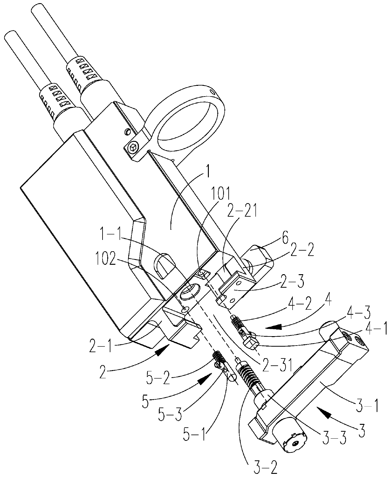
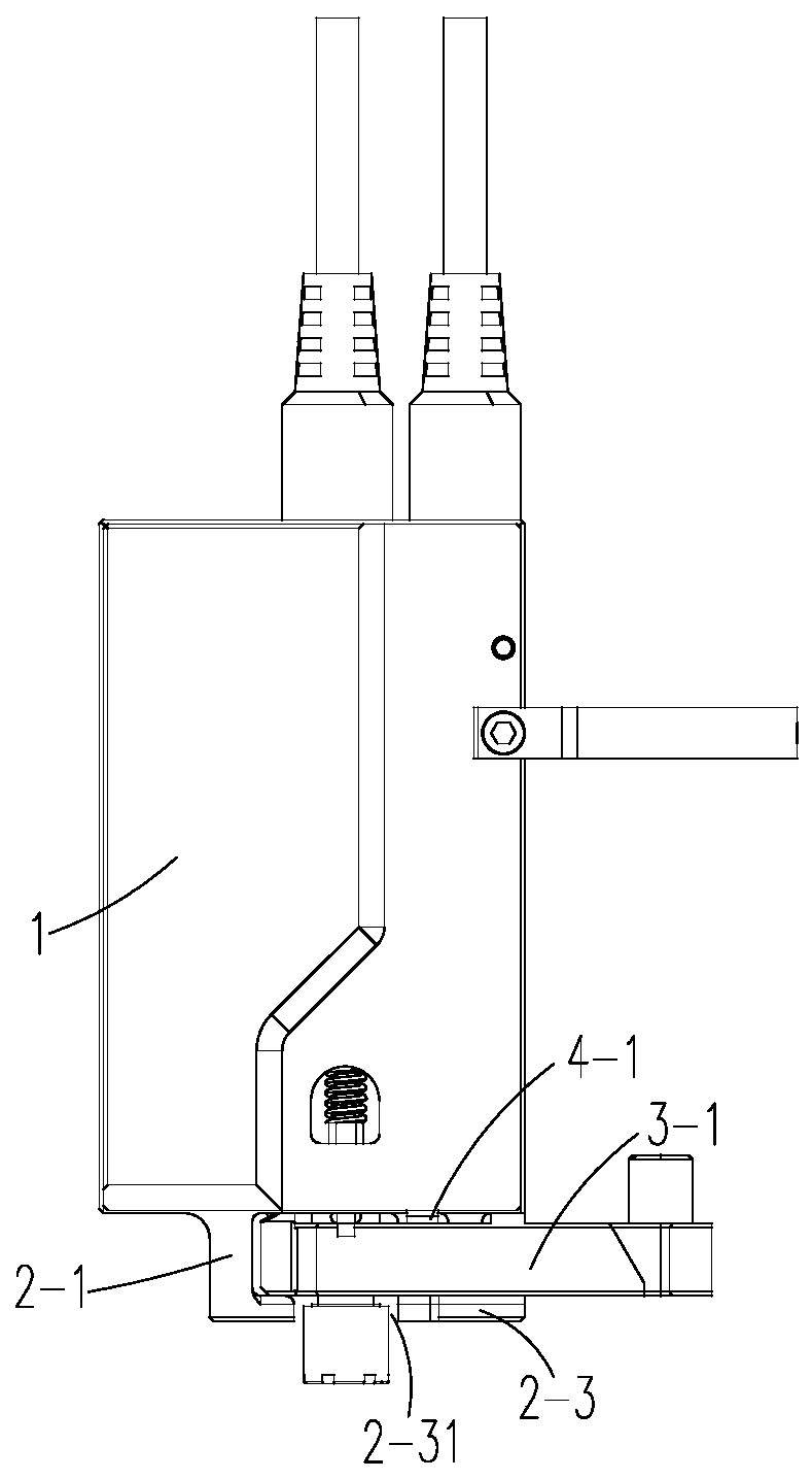
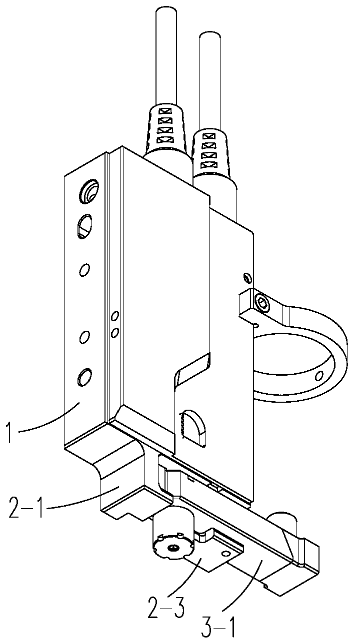
[0055] Such as Figure 1-11 As shown, a quick loading and unloading flow channel device is used for piezoelectric injection valves. The piezoelectric injection valves include a valve body 1, a mounting part 2 at the bottom of the valve body 1 and a push rod installation hole 1-1. The flow channel Devices include:

[0056] The flow channel assembly 3 has a flow channel body 3-1 and an injection push rod 3-2 arranged on the flow channel body 3-1. The installation part 2 of the valve body 1 is provided with a flow channel body 3-1 The loading position 7 of the installation part 2 and the working position 8 where the flow channel body 3-1 is working. When the flow channel body 3-1 is inserted into the loading position 7, the injection push rod 3-2 will also be located In the push rod installation hole 1-1; wherein, the runner body 3-1 can rotate along the installation direction and the disassembly direction opposite to the installation direction with the axis of the injection pus...

Embodiment 2

[0083] The difference between embodiment 2 and embodiment 1 is that the locking units used are different, as follows:

[0084] Such as Figure 12 As shown, the locking unit includes a main preload assembly 4, the main preload assembly 4 has an elastically retractable compression block 4-1, and the runner body 3-1 is installed from the loading position 7 along the When the direction is rotated to the working position 8, the flow channel body 3-1 will overcome the elasticity on the compression block 4-1 to force the compression block 4-1 to displace, and after the flow channel body 3-1 reaches the working position 8, it will convect the flow channel. The body 3 - 1 generates a certain pre-tightening force to press it against the installation part 2 .

[0085] One end of the compression block 4-1 in the main preload assembly 4 is fixed on the valve body 1, and the other end is tilted towards the flow channel body 3-1 at the working position 8; thus, the compression block 4-1 its...

Embodiment 3

[0098] The difference between embodiment 3 and implementation 2 or 3 is that the locking units used are different, as follows:

[0099] Such as Figure 13 As shown, the locking unit includes a locking screw 6 arranged on the mounting part 2, the upper surface of the flow channel body 3-1 at the working position 8 is in contact with the bottom surface of the valve body 1, and the flow channel at the working position 8 The lower surface of the body 3-1 is in contact with the installation part 2, and the locking screw 6 is screwed to the flow channel body 3-1 at the working position 8.

[0100] Such as figure 2 , 3 As shown in and 13, the installation part 2 includes a right side plate 2-1 fixed on the right side of the bottom surface of the valve body 1, a rear side plate 2-2 fixed on the rear side of the bottom surface of the valve body 1, and relatively fixed on the right side plate 2. -1 and the bottom side plate 2-3 at the bottom of the rear side plate 2-2, the flow chan...


PUM


Abstract

The invention relates to the technical field of flow channel assemblies of piezoelectric injection valves, in particular to a quick assembling and disassembling flow channel device. The flow channel device is used for the piezoelectric injection valve. The flow channel device comprises the flow channel assembly and a valve body, wherein an installation part of the valve body is provided with a loading position for building a flow channel body into the installation part and a working position at which the flow channel body works; and the flow channel body is capable of rotating along the assembling direction and the disassembling direction opposite to the assembling direction. According to the flow channel device, the flow channel body can be assembled and disassembled in a rotating mode, the mode is novel and does not need the help of auxiliary tools during assembly and disassembly, and the operation is very convenient and fast, so that the maintenance process of the piezoelectric injection valve is simplified, and the maintenance time is saved; and meanwhile, the flow channel assembly can be firmly fixed on the valve body, so that vibration of the flow channel body caused by high-frequency vibration of the piezoelectric injection valve is prevented, and the dispensing effect is effectively improved.

Description

technical field [0001] The present invention relates to the technical field of flow channel assemblies of piezoelectric injection valves, in particular to a quick-loading and detachable flow channel device. In addition, the present invention also relates to a piezoelectric injection valve including the above-mentioned quick-loading and detachable flow channel device and a A dispenser for the piezoelectric injection valve described above. Background technique [0002] With the rapid development of the electronics industry, the requirements for electronic packaging are getting higher and higher. For the high-demand electronic packaging technology, non-contact injection valves are more and more widely used in the field of electronic packaging due to their high efficiency and high precision. The piezoelectric stack with high response speed and high precision is the core driving component of the non-contact piezoelectric injection valve, and it is also widely used in non-contact ...

Claims


Application Information

Patent Timeline
IPC IPC(8): B05C5/02B05C11/10
CPCB05C5/0225B05C11/1026F16K31/004F16K17/042
Inventor 崔建松顾守东刘建芳
Owner CHANGZHOU GAO KAI PRECISION MACHINERY CO LTD
Why Eureka
Try Eureka