Inductively coupled plasma processing system

A plasma and inductive coupling technology, applied in the direction of circuits, discharge tubes, electrical components, etc., can solve the problems of reducing the production efficiency of plasma processing equipment, uneven window cleaning, and difficult maintenance in the later stage, so as to simplify equipment installation and maintenance, Save a lot of space and make easy effects

Active Publication Date: 2019-11-05
JIANGSU LEUVEN INSTR CO LTD
View PDF5 Cites 15 Cited by
  • Summary
  • Abstract
  • Description
  • Claims
  • Application Information

AI Technical Summary

Problems solved by technology

[0005] Technical problem to be solved: This application mainly proposes an inductively coupled plasma processing system to solve technical problems in the prior art such as local sputtering damage, uneven window cleaning, difficulty in later maintenance, and reduced production efficiency of plasma processing equipment.

Method used


Image

  • Inductively coupled plasma processing system
  • Inductively coupled plasma processing system
  • Inductively coupled plasma processing system

Examples


Embodiment 1

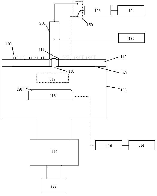
[0034] Such as figure 1 As shown, an inductively coupled plasma processing system, the inductively coupled plasma processing system includes a plasma reaction chamber 102, an excitation RF power supply 104, a matching network A106, a RF coil 108, a dielectric window 110, and a bias RF power supply 114 , matching network B116, electrode 118, substrate sheet 120, gas source 130, gas inlet 140, pressure control valve 142, vacuum pump 144 and three-way switch 150, the excitation RF power supply 104 is tuned through the matching network A106, and then passed through three Power is supplied to the RF coil 108 above the dielectric window 110 through the switch 150, and the plasma 112 is generated in the plasma reaction chamber 102 through inductive coupling. The bias RF power supply 114 provides power for the electrode 118 through the matching network B116, and the substrate sheet 120 is placed Above the electrode 118; the radio frequency coil 108 includes ≥ 2 sub-coils, and the radi...

Embodiment 2

[0040] Such as figure 1 As shown, an inductively coupled plasma processing system, the inductively coupled plasma processing system includes a plasma reaction chamber 102, an excitation RF power supply 104, a matching network A106, a RF coil 108, a dielectric window 110, and a bias RF power supply 114 , matching network B116, electrode 118, substrate sheet 120, gas source 130, gas inlet 140, pressure control valve 142, vacuum pump 144 and three-way switch 150, the excitation RF power supply 104 is tuned through the matching network A106, and then passed through three Power is supplied to the RF coil 108 above the dielectric window 110 through the switch 150, and the plasma 112 is generated in the plasma reaction chamber 102 through inductive coupling. The bias RF power supply 114 provides power for the electrode 118 through the matching network B116, and the substrate sheet 120 is placed Above the electrode 118; the radio frequency coil 108 includes ≥ 2 sub-coils, and the radi...


PUM


Abstract

The invention discloses an inductively coupled plasma processing system which switches the connection of radio frequency power between a radio frequency coil and a Faraday shielding device via a switch. When a radio frequency power supply is connected with the radio frequency coil through a matching network, the radio frequency power is coupled into the radio frequency coil for plasma processing.When the radio frequency power supply is connected with the Faraday shielding device through the matching network, the radio frequency power is coupled into the Faraday shielding device to clean the dielectric window and the inner wall of the plasma processing chamber. Meanwhile, the Faraday system and the dielectric window are one component so that installation and maintenance of the radio frequency coil can be facilitated and efficient cleaning of the inner wall of the plasma processing chamber, especially the dielectric window, can be realized.

Description

technical field [0001] The invention belongs to the technical field of Faraday shielding systems, in particular to an inductively coupled plasma processing system. Background technique [0002] At present, non-volatile materials such as Pt, Ru, Ir, NiFe, and Au are mainly dry-etched by inductively coupled plasma (ICP). Inductively coupled plasma is typically generated by coils positioned outside the plasma processing chamber adjacent to a dielectric window, and process gases within the chamber are ignited to form the plasma. But inevitably and at the same time somewhat unwelcome, the voltage between different parts of the plasma coil capacitively couples into the plasma, and while this coupling facilitates ignition and stabilization, the capacitively coupled parts can cause localized Intensify the voltage, which may accelerate ions leaving the plasma to locally affect the dielectric window, resulting in localized sputtering damage. In other cases, capacitive coupling may...

Claims


Application Information

Patent Timeline
Patent Type & Authority Applications(China)
IPC IPC(8): H01J37/32
CPCH01J37/321H01J37/32431H01J37/32651H01J37/32862H01J2237/334H01J37/32183H01J37/32477H01J37/32119
Inventor 刘海洋刘小波李雪冬李娜程实然郭颂胡冬冬许开东
Owner JIANGSU LEUVEN INSTR CO LTD
Why Eureka
Try Eureka