Check patentability & draft patents in minutes with Patsnap Eureka AI!

Limiting device

A technology of a limit device and a limit piece, which is applied in the directions of packaging, transportation, packaging, and closing, and can solve problems such as failure of the push rod lock and lock point.

Inactive Publication Date: 2019-09-20
深圳市欣旺达综合能源服务有限公司
View PDF4 Cites 0 Cited by
  • Summary
  • Abstract
  • Description
  • Claims
  • Application Information

AI Technical Summary

Problems solved by technology

[0004] The main purpose of the present invention is to provide a limit device, aiming to solve the problem that the locking point of the push rod lock becomes invalid due to the vibration of the existing energy storage equipment box during transportation and hoisting

Method used


Image

  • Limiting device
  • Limiting device
  • Limiting device

Examples


Embodiment Construction

[0021] It should be understood that the specific embodiments described here are only used to explain the present invention, not to limit the present invention.

[0022] The following is attached figure 1 - attached image 3 The present invention is further described in detail.

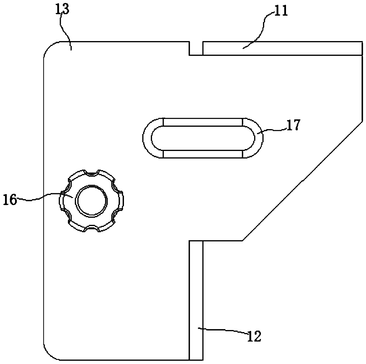
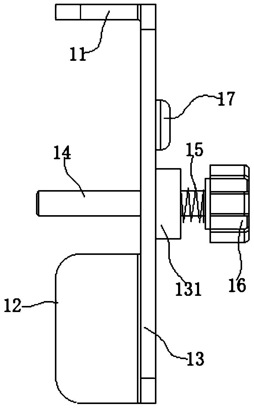
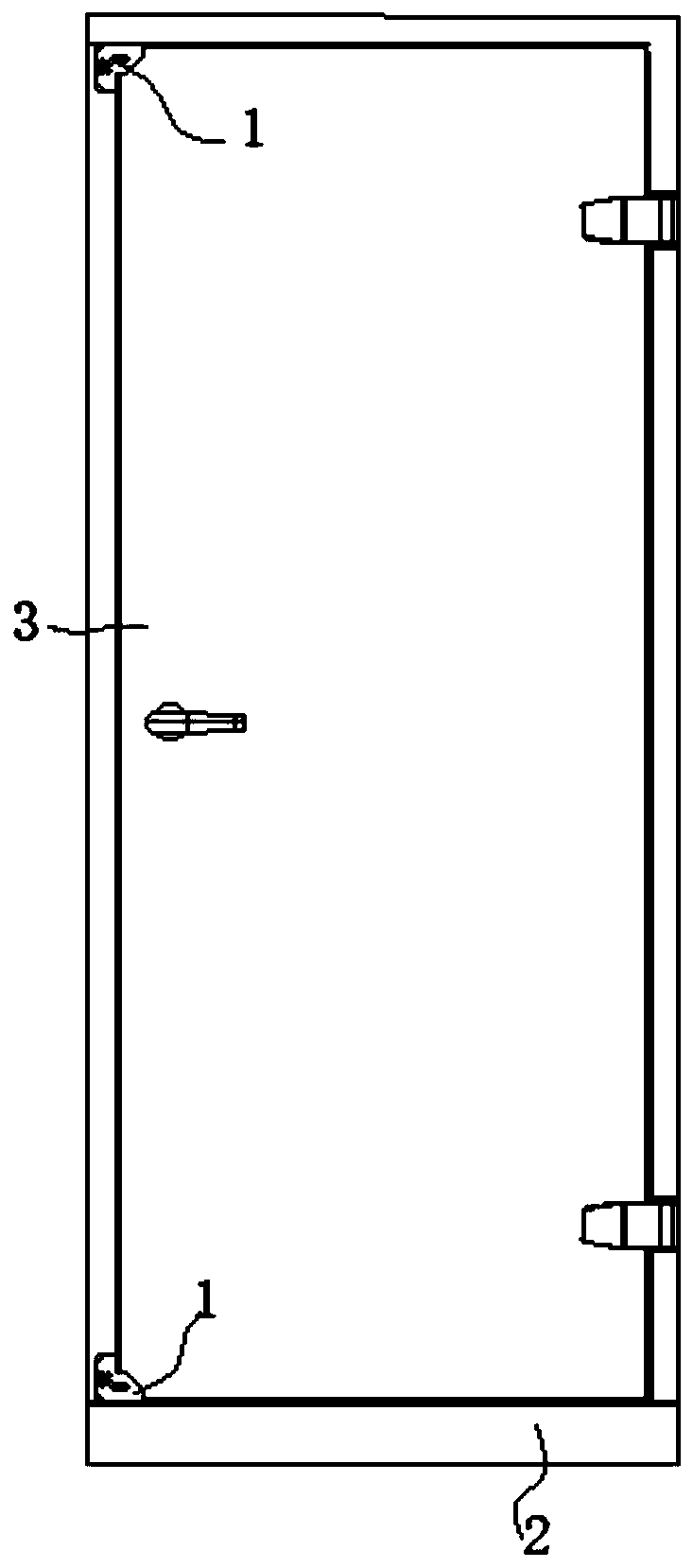
[0023] A limit device 1, combined with figure 1 and figure 2 and image 3 , installed at the corner of door 3 corresponding to the opening end of door 3 on door frame 2, including: X-axis limiter 11, Y-axis limiter 12, Z-axis limiter 13; X-axis limiter 11 and Y-axis limiter 12 is set on the same side of the Z-axis limiter 13; when in use, the Z-axis limiter 13 is fixedly installed on the door frame 2, and is located on the side of the door frame 2 away from the opening direction of the door 3, and the Z-axis limiter 13 has a direction toward The extension part extending in the direction of the door 3, the extension part limits the rotation of the door 3 towards the direction of the extension part...


PUM


Abstract

The invention discloses a limiting device. The limiting device is installed at a door corner, corresponding to the opening end of a door, of a door frame and comprises an X-axis limiting piece, a Y-axis limiting piece and a Z-axis limiting piece. The X-axis limiting piece and the Y-axis limiting piece are arranged on the same side of the Z-axis limiting piece. During use, the Z-axis limiting piece is fixedly arranged on the door frame and is located on one side, away from the door opening direction, of the door frame, wherein the Z-axis limiting piece is provided with an extending part extending towards the direction of the door, and the extending part is used for limiting the rotation of the door towards the direction where the extending part is located; the X-axis limiting piece is embedded in a horizontal gap between the door frame and the door; and the Y-axis limiting piece is embedded in a vertical gap between the door frame and the door. The limiting device aims to solve the problem that a lock point of a push rod lock loses effect due to vibration of an existing energy storage equipment box in transportation and lifting processes.

Description

technical field [0001] The invention relates to the design field of energy storage equipment boxes, in particular to a limiting device. Background technique [0002] The energy storage equipment box is a special container that integrates intelligent integration of uninterruptible power supply, battery pack, precision air conditioner, and monitoring equipment. It meets the requirements of environmental protection, has heat insulation and constant temperature, fire-fighting and flame-retardant functions, and has anti-rain, anti-fog, dust-proof, wind-sand, lightning-proof, and anti-theft effects, etc., to meet various use environments. [0003] The energy storage equipment box is equipped with a fire door, which needs to be kept locked during normal use; in order to facilitate escape, the fire door is equipped with a push rod lock with a quick escape operation, and the push rod lock has only one bolt. That is, there is only one locking point; however, the energy storage equipm...

Claims


Application Information

Patent Timeline
IPC IPC(8): B65D59/00
CPCB65D59/00
Inventor 赵伟刘明爽
Owner 深圳市欣旺达综合能源服务有限公司
Features
  • R&D
  • Intellectual Property
  • Life Sciences
  • Materials
  • Tech Scout
  • Unparalleled Data Quality
  • Higher Quality Content
  • 60% Fewer Hallucinations
Learn More