Energy-saving control system and control method for vibrating road roller, and vibrating road roller

An energy-saving control system and vibratory roller technology, applied in roads, roads, road repairs, etc., can solve problems such as waste of energy and high noise, and achieve the effects of improving reliability, reducing fuel consumption, and maintaining work efficiency

Active Publication Date: 2019-09-20
SANY AUTOMOBILE MFG CO LTD
View PDF14 Cites 16 Cited by
  • Summary
  • Abstract
  • Description
  • Claims
  • Application Information

AI Technical Summary

Problems solved by technology

When vibration is required, press the vibration button, and the vibration wheel will achieve a stable vibration frequency (because the engine speed remains unchanged) to compact the road surface, but the engine is always at the maximum speed, which wastes energy and is noisy

Method used


Image

  • Energy-saving control system and control method for vibrating road roller, and vibrating road roller
  • Energy-saving control system and control method for vibrating road roller, and vibrating road roller
  • Energy-saving control system and control method for vibrating road roller, and vibrating road roller

Examples


Embodiment Construction

[0053] In order to understand the above-mentioned purpose, features and advantages of the present invention more clearly, the present invention will be further described in detail below in conjunction with the accompanying drawings and specific embodiments. It should be noted that, in the case of no conflict, the embodiments of the present application and the features in the embodiments can be combined with each other.

[0054] In the following description, many specific details are set forth in order to fully understand the present invention. However, the present invention can also be implemented in other ways different from those described here. Therefore, the protection scope of the present invention is not limited by the specific details disclosed below. EXAMPLE LIMITATIONS.

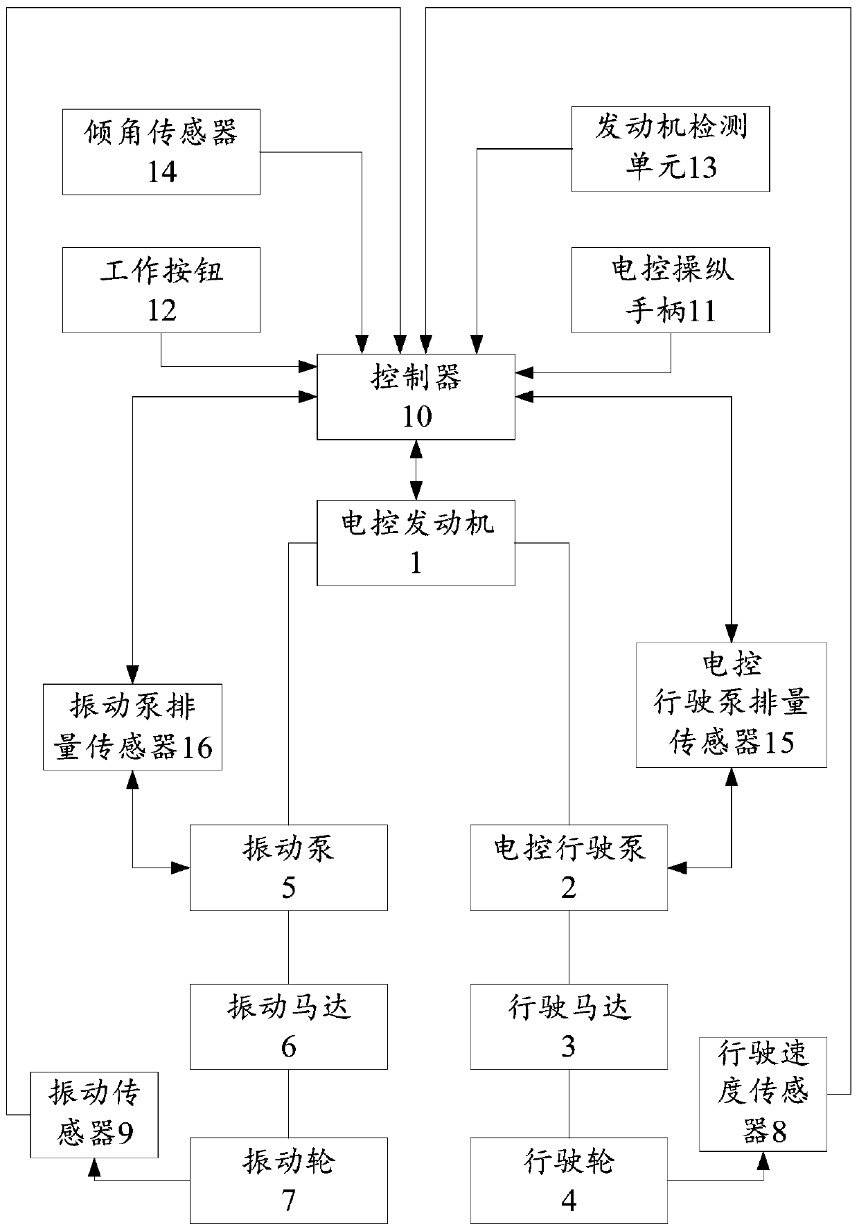
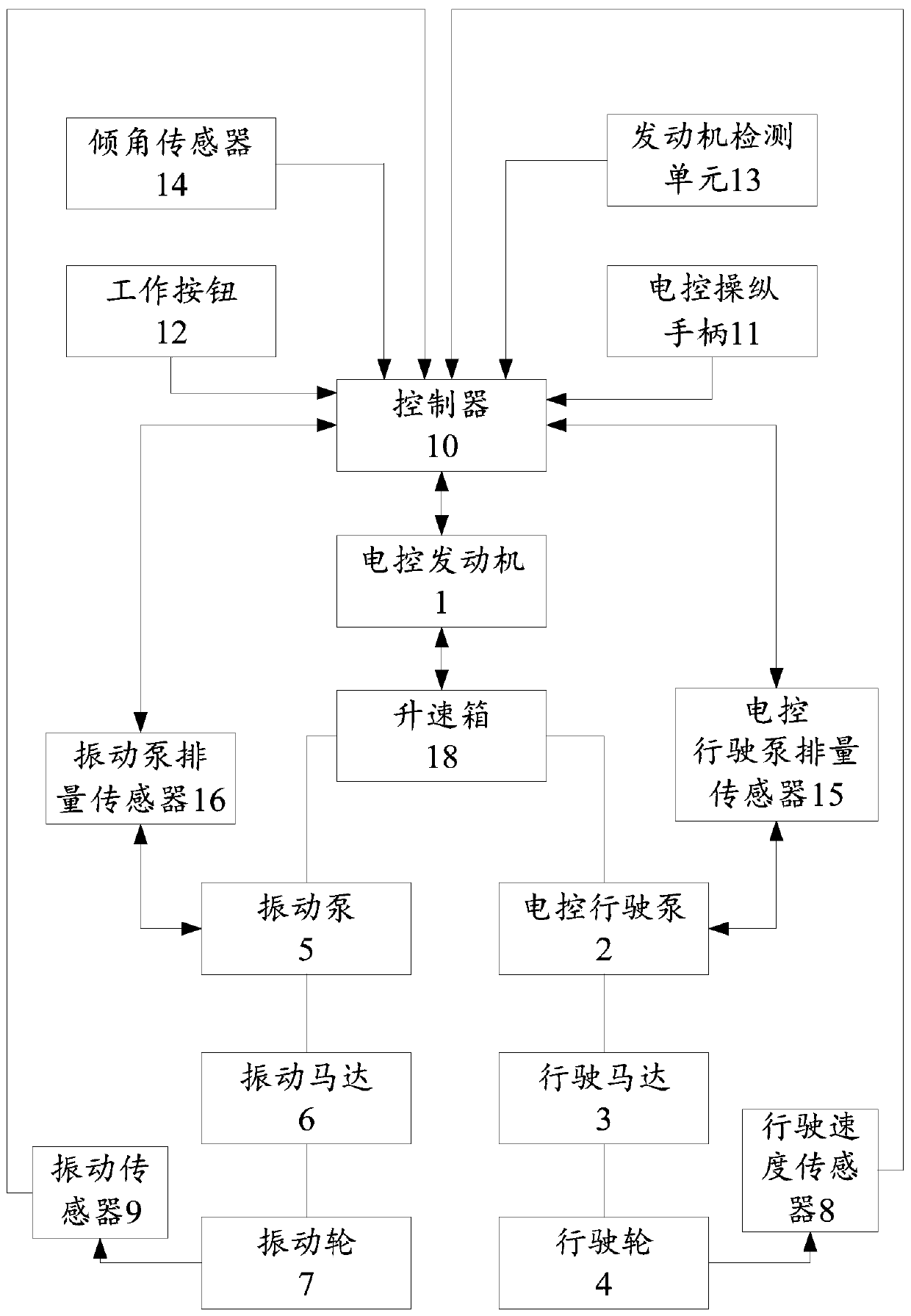
[0055] Refer below Figure 2 to Figure 8 The vibratory roller energy-saving control system, the control method of the vibratory roller energy-saving control system and the vibratory roller according...


PUM


Abstract

The invention provides an energy-saving control system and control method for a vibrating road roller, and the vibrating road roller. The energy-saving control system for the vibrating road roller comprises an electronically-controlled operation handle, a controller, an electronically-controlled engine, an electronically-controlled running pump, a running module and a running system, wherein the electronically-controlled engine, the electronically-controlled running pump, the running module and the running system are sequentially connected; the controller is connected with the electronically-controlled engine, the electronically-controlled running pump and the electronically-controlled operation handle; and the controller is capable of adjusting the rotational speed of the electronically-controlled engine and the displacement of the electronically-controlled running pump according to the position of the electronically-controlled operation handle. Through the energy-saving control system and control method for the vibrating road roller, and the vibrating road roller, the controller is capable of adjusting the rotational speed of the electronically-controlled engine and the displacement of the electronically-controlled running pump according to the position of the electronically-controlled operation handle, and the electronically-controlled engine is enabled to work at a good rotational speed, so that the purposes of energy saving and noise reduction of the electronically-controlled engine are realized; and meanwhile, the displacement of the electronically-controlled running pump is automatically adjusted through the controller to meet the power need of the whole system, so that the working stability and reliability of the system are ensured.

Description

technical field [0001] The invention relates to the technical field of vibratory road rollers, in particular to an energy-saving control system for vibratory road rollers, a control method for the energy-saving control system for vibratory road rollers, and a vibratory road roller. Background technique [0002] The current vibratory road roller generally includes two systems: a traveling system and a vibrating system. The traveling system enables the road roller to perform static rolling on the road surface before and after to realize road surface compaction; Driving compaction and vibratory compaction are carried out at the same time, and the road surface can also be statically rolled by driving alone. Now, the single-drum vibratory roller is taken as an example to illustrate the system. The transmission route of the traveling system is the engine, the traveling hydraulic pump, the traveling hydraulic motor, the rear axle and the tires. Among them, there are two ways to re...

Claims


Application Information

Patent Timeline
Patent Type & Authority Applications(China)
IPC IPC(8): E01C19/28
CPCE01C19/282
Inventor 贾干段乾坤黄必粹
Owner SANY AUTOMOBILE MFG CO LTD
Why Eureka
Try Eureka