Sample analyzer and sample rack transfer structure

A sample analyzer and sample holder technology, applied in the direction of analyzing materials, instruments, etc., can solve the problems of inconvenience and high cost, and achieve the effects of convenient use, light weight, and improved operating feel

Pending Publication Date: 2019-09-24
SHENZHEN MINDRAY BIO MEDICAL ELECTRONICS CO LTD
View PDF9 Cites 2 Cited by
  • Summary
  • Abstract
  • Description
  • Claims
  • Application Information

AI Technical Summary

Problems solved by technology

[0003] Based on this, it is necessary to solve the problems of high cost and inconvenient use caused by the complexity of the current anti-off mechanism, and provide a sample rack

Method used


Image

  • Sample analyzer and sample rack transfer structure
  • Sample analyzer and sample rack transfer structure
  • Sample analyzer and sample rack transfer structure

Examples


Embodiment Construction

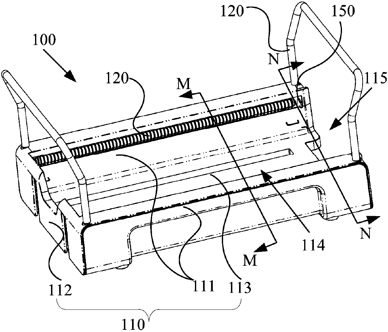
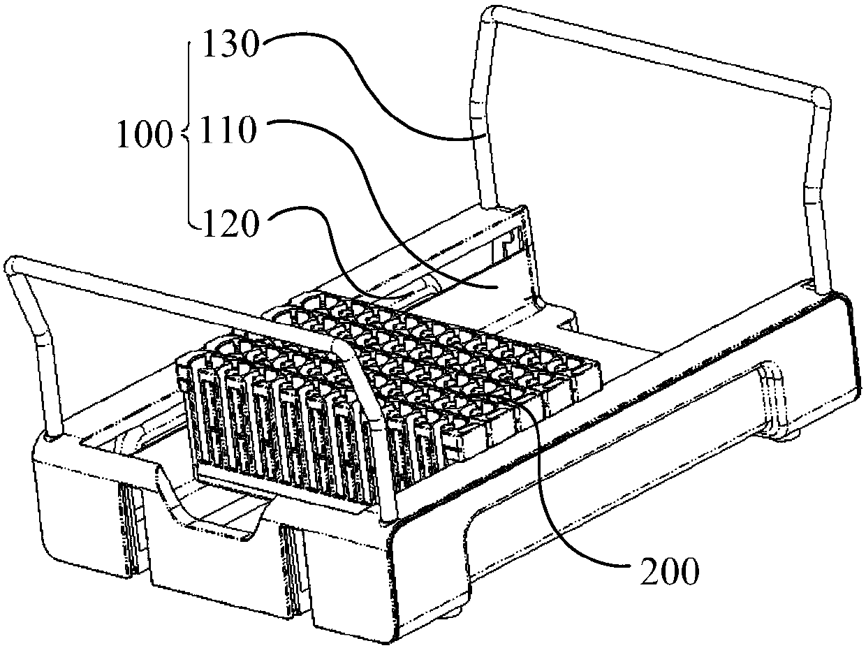
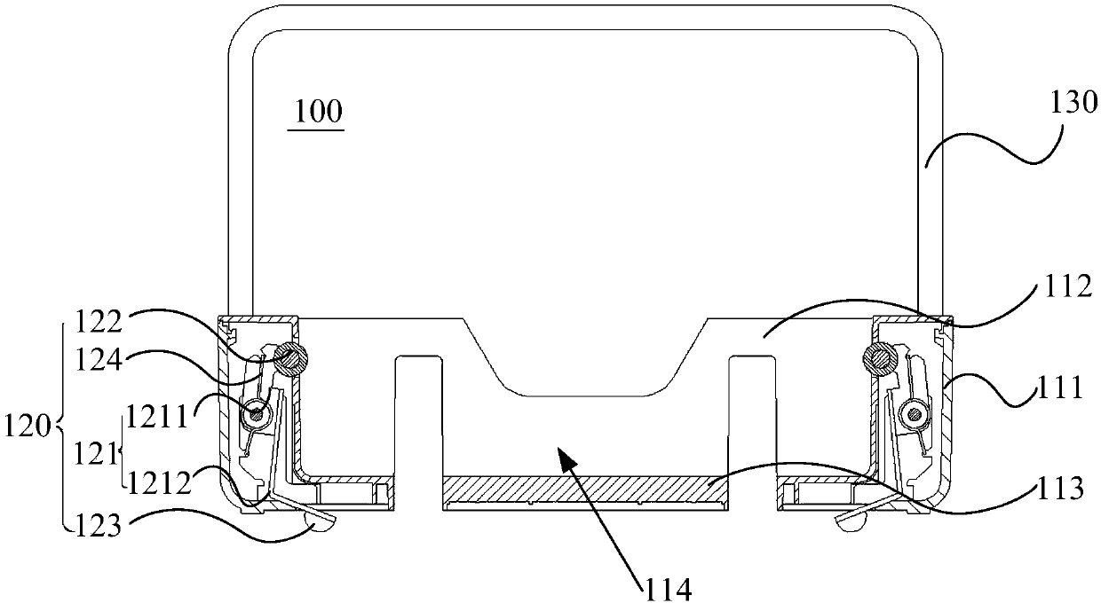
[0082] In order to make the purpose, technical solution and advantages of the present invention clearer, the sample analyzer and the sample rack transfer structure of the present invention will be further described in detail through the following examples and in conjunction with the accompanying drawings. It should be understood that the specific embodiments described here are only used to explain the present invention, not to limit the present invention.

[0083] The serial numbers assigned to components in this document, such as "first", "second", etc., are only used to distinguish the described objects, and do not have any sequence or technical meaning. The "connection" and "connection" mentioned in this application all include direct and indirect connection (connection) unless otherwise specified. In describing the present invention, it is to be understood that the terms "upper", "lower", "front", "rear", "left", "right", "vertical", "horizontal", "top", The orientation o...


PUM


Abstract

The invention provides a sample rack transfer structure. The structure includes a carrying tray which is provided with a placement cavity and an opening communicating with the placement cavity at one side of the placement cavity, wherein the placement cavity is used for carrying sample racks arranged in rows and an arrangement direction of the sample racks extends toward the opening, an anti-slip mechanism which is arranged on the inner side wall of the carrying tray, near the opening and is used for preventing the sample racks from sliding out of the carrying tray, and an unlocking mechanism which is arranged on the analyzer and used for unlocking the anti-slip mechanism. When the carrying tray is lifted, the anti-slip mechanism can extend into the placement cavity to restrict the sample racks from sliding out of the placement cavity. The carrying tray is placed on the sample analyzer. The unlocking mechanism cooperates with the anti-slip mechanism. The anti-slip mechanism unlocks the sample racks. The carrying tray is placed on a desktop. The anti-slip mechanism restricts the sample racks from sliding out of the placement cavity. The locking operation of the anti-slip mechanism is simple and fast, and the unlocking operation of the unlocking mechanism is simple, which facilitates the use. The invention also provides the sample analyzer.

Description

technical field [0001] The invention relates to the technical field of chemiluminescence immunoassay, in particular to a sample analyzer and a sample rack transfer structure. Background technique [0002] Usually, the anti-off mechanism on the front side of the tray limits the position of the sample rack. However, when the tray is installed on the equipment platform, the anti-off structure on the front side is unlocked through the unlocking mechanism on the equipment platform, and the tray can push the sample rack placed inside it to the outer transmission track through the pushing device. The unlocking mechanism adopts the bracket falling prevention mechanism to cooperate with the front side anti-off mechanism. The front side anti-off mechanism gradually moves along the bracket off-prevention mechanism during the loading process. After the front side anti-off mechanism is installed in place, the bracket off-prevention mechanism moves and drives The front side anti-off mech...

Claims


Application Information

Patent Timeline
IPC IPC(8): G01N35/04
CPCG01N35/04
Inventor 常先华刘峰张乐平高再兴
Owner SHENZHEN MINDRAY BIO MEDICAL ELECTRONICS CO LTD
Why Eureka
Try Eureka