AI technical title is built by Patsnap AI team. It summarizes the technical point description of the patent document.
A combined and adjustable technology, applied in the directions of outer plate, inner bone synthesis, fixator, etc., can solve the problems of the change of the external size of the bone plate, the sliding displacement of the connecting rod, and the different angles.
Inactive Publication Date: 2019-09-27
AFFILIATED YONGCHUAN HOSPITAL OF CHONGQING MEDICAL UNIV
View PDF3 Cites 3 Cited by
Summary
Abstract
Description
Claims
Application Information
AI Technical Summary
This helps you quickly interpret patents by identifying the three key elements:
Problems solved by technology
Method used
Benefits of technology
Problems solved by technology
[0005] First, since the two ends of the connecting rod are respectively inserted into the holes of the two longitudinal plates, if the connecting rod is threadedly matched with the holes, when the connecting rod rotates due to the movement of the patient, the connecting rod will Rotation with the threaded hole of the longitudinal plate causes longitudinal displacement, the shape and size of the bone plate changes, and there is a simultaneous deviation of the bone screws on the two longitudinal plates, resulting in a risk of loosening;
[0006] Second, because the two ends of the connecting rod are respectively inserted into the cavities of the two longitudinal plates, if the slit opening is reduced by the large top fixing screw and the connecting rod is clamped by the cavity, the connecting rod It is in contact with the smooth surface of the cavity, and the clamping force is generated by the narrowing of the slit opening. The friction force between the connecting rod and the cavity is very small, and the connecting rod is easy to slide in the cavity. The bone plate Dimensions change, there is a simultaneous deviation of the bone screws on the two longitudinal plates, and there is a risk of loosening;
[0007] Third, when the bone screw is installed in the bone screw hole on the bone plate, the direction of the bone screw cannot be adjusted.
Method used
Image
Click on the blue label to locate the original text in one second.
Reading with bidirectional positioning of images and text.
Examples
Embodiment 1
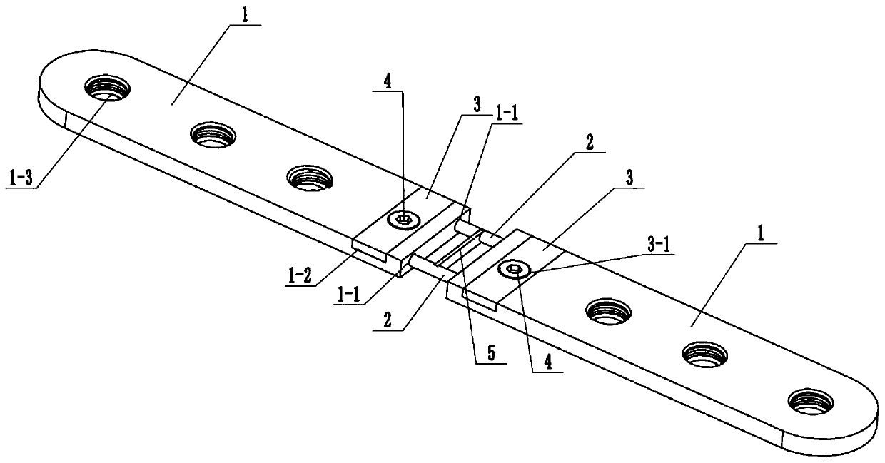
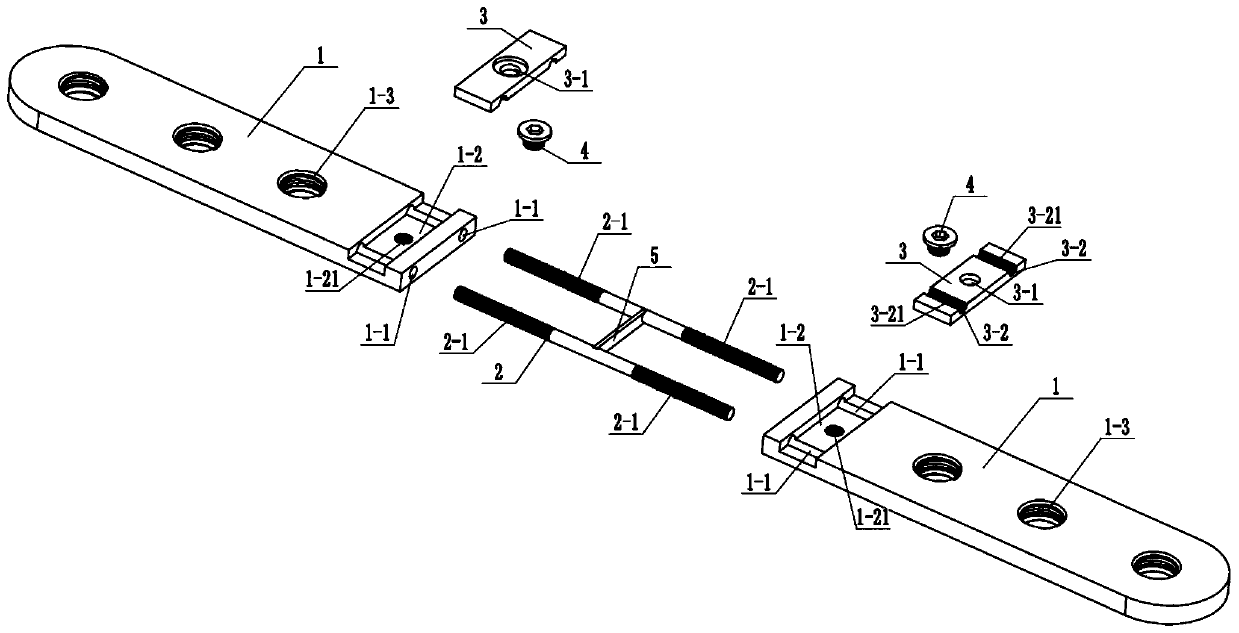
[0038] Example 1: see Figure 1-5 , An adjustable combined bone nail plate, which includes two bone plates 1, two adjusting rods 2, two pressure plates 3 and two first screws 4.
[0039] In this embodiment, the two bone plates 1 are strip-shaped plates, and the two bone plates 1 are arranged oppositely and distributed symmetrically.
[0040] Specifically, in this embodiment, the two bone plates 1 are distributed collinearly.
[0041] The two bone plates 1 are provided with two first adjusting holes 1-1 on the opposing surfaces, and the two first adjusting holes 1-1 are distributed in parallel and spaced apart.
[0042] Preferably, the direction of the centerline of the first adjustment hole 1-2 and the length direction of the two bone plates 1 are parallel to each other.
[0043] Wherein, the outer side walls of both ends of the two adjusting rods 2 are provided with annular grooves 2-1 distributed at equal intervals.
[0044] Preferably, the depth of the annular groove 2-1 is greater th...
Embodiment 2
[0065] Embodiment 2: see Figure 6-8 This embodiment is basically the same as the first embodiment, but the difference is that: the first embodiment described above adopts a bone plate 1 with a plurality of bone nail mounting holes 1-3. In this embodiment, the bone plate 1 is provided with second adjustment holes 1-4.
[0066] Can see Figure 6-8 In addition, this embodiment also includes a ball head 6, a second screw 7, and a pressing rod 8.
[0067] Wherein, the second adjusting hole 1-4 includes a ball mouth portion 1-41 and a bell mouth portion 1-42.
[0068] Specifically, the shape of the mouth portion 1-41 is small at both ends and large in the middle, and the big end of the bell mouth portion 1-42 faces outward and away from the mouth portion 1-41.
[0069] The direction-adjusting ball head 6 is fitted in the ball mouth portion 1-41, and the direction-adjusting ball head 6 is provided with a bone nail hole 6-1 for the head 9-1 of the bone nail 9 to be fitted.
[0070] In this em...
PUM
Abstract
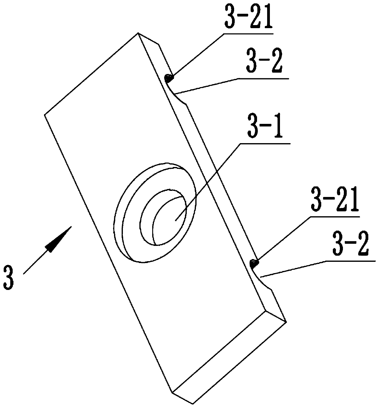
The invention discloses an adjustable combined type bone peg plate. The adjustable combined type bone peg plate is characterized by comprising two bone plates, two adjusting rods, two press plates and two first screws, wherein two first adjusting holes are respectively formed in opposite surfaces of the two bone plates; annular grooves which are distributed at equal intervals are formed in the outer side walls of the two end parts of each of the two adjusting rods; two press plate clamp grooves are formed in the front surfaces of the two bone plates respectively and each press plate clamp groove is communicated with the two corresponding first adjusting holes; one end parts of the two adjusting rods are inserted into the two first adjusting holes of one bone plate respectively, and the other end parts of the two adjusting rods are inserted into the two first adjusting holes of the other bone plate respectively; two arc-shaped grooves are formed in the inner surface of each of the two press plates and matched with the end parts of the adjusting rods in shape, and arc-shaped clamp bosses inserted into the annular grooves are arranged on the inner walls of the arc-shaped grooves. With the adoption of structural design different from a conventional adjusting mode, the problems of loosening and poor reliability can be solved.
Description
Technical field [0001] The invention belongs to an adjustable combined bone nail plate. Background technique [0002] In the treatment of bone fractures and other orthopedic diseases, it is necessary to use a combination of bone nails and bone plates to fix the position around the fracture. [0003] According to the bone type characteristics of different patients, it is necessary to adjust the spacing or angle of the bone nails on the bone plate to achieve the best working state of the bone nail and the bone plate. However, the position and angle of the bone nail mounting holes on the bone plates on the existing market are not adjustable. [0004] In addition, an adjustable bone plate (publication number CN 101056590B) has been disclosed, which can adjust the length of the bone plate. However, the following shortcomings still exist and are analyzed as follows: [0005] First, because the two ends of the connecting rod are inserted into the cavities of the two longitudinal plates, if...
Claims
Application Information
Patent Timeline
Application Date:The date an application was filed.
Publication Date:The date a patent or application was officially published.
First Publication Date:The earliest publication date of a patent with the same application number.
Issue Date:Publication date of the patent grant document.
PCT Entry Date:The Entry date of PCT National Phase.
Estimated Expiry Date:The statutory expiry date of a patent right according to the Patent Law, and it is the longest term of protection that the patent right can achieve without the termination of the patent right due to other reasons(Term extension factor has been taken into account ).
Invalid Date:Actual expiry date is based on effective date or publication date of legal transaction data of invalid patent.
Patent Type & AuthorityApplications(China)
IPC IPC(8): A61B17/80A61B17/86
CPCA61B17/8057A61B17/8605
Inventor陈代鸿
OwnerAFFILIATED YONGCHUAN HOSPITAL OF CHONGQING MEDICAL UNIV

