Pipe body cutting device and working method thereof

A technology of cutting device and working method, applied in copper tube cutting and aluminum fields, can solve the problems of easy bending of saw blades, affect quality, increase de-flashing process, etc., and achieve the effect of good cutting quality and high cutting efficiency

Pending Publication Date: 2019-09-27
CHANGZHOU INST OF LIGHT IND TECH
View PDF0 Cites 0 Cited by
  • Summary
  • Abstract
  • Description
  • Claims
  • Application Information

AI Technical Summary

Problems solved by technology

Since the extruded pipe is still in a high temperature state and is relatively soft, it is easy to bend when cutting in one direction with a traditional sa

Method used


Image

  • Pipe body cutting device and working method thereof
  • Pipe body cutting device and working method thereof
  • Pipe body cutting device and working method thereof

Examples


Embodiment 1

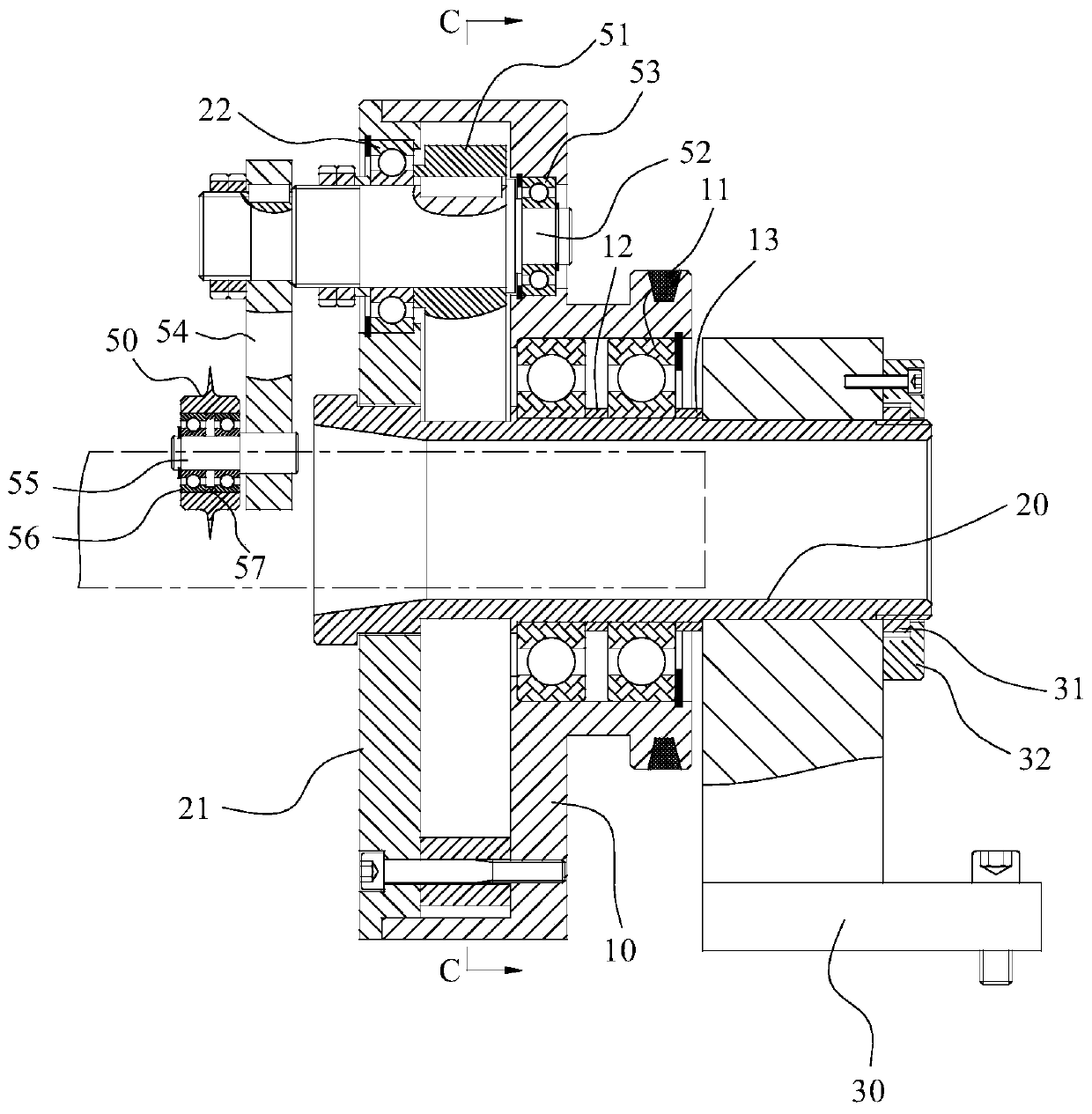
[0024] Such as Figure 1 to Figure 4 As shown, the present embodiment 1 provides a pipe body cutting device, including: a rotary disk 10, a cutting mechanism located on the rotary disk 10, and a driving mechanism; wherein the center of the rotary disk 10 is provided with a through hole to piercing the pipe body; and the driving mechanism is suitable for driving the rotary disk 10 to rotate, so as to drive the cutting structure to rotate to cut the pipe body.

[0025] The rotating disk 10 is sleeved on a supporting shaft 20 ; and the supporting shaft 20 is located on a supporting seat 30 .

[0026] Specifically, the support shaft 20 is installed on the support seat 30, and is locked by the first nut 31 and the gland 32; the rotary table 10 is installed on the support shaft 20 by the first bearing 11; the second A bearing 11 is axially fixed by a first spacer 12 and a second spacer 13 .

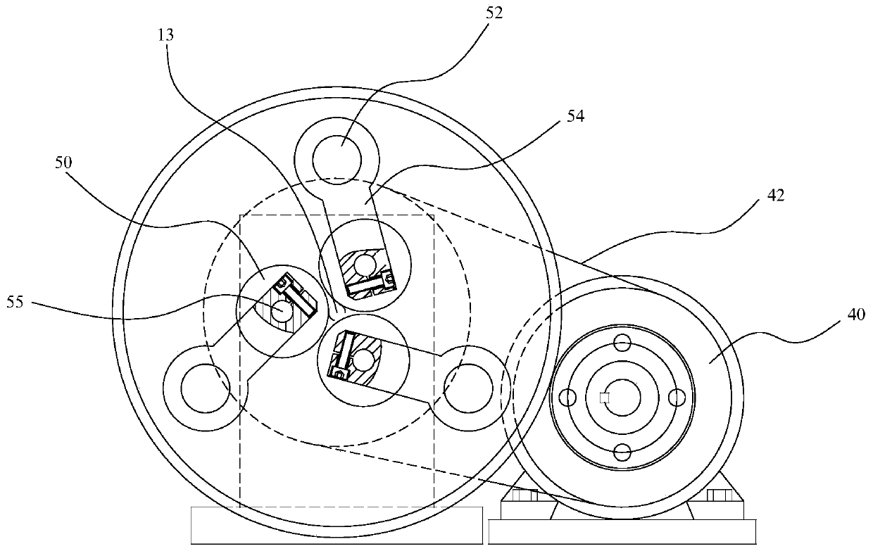
[0027] The drive mechanism includes: a motor 40 and a transmission wheel 41 positioned at...

Embodiment 2

[0040] On the basis of embodiment 1, this embodiment 2 provides a working method of a pipe body cutting device, including: piercing the pipe body from the center of the rotary disk; The cutting structure on the turntable rotates to cut the pipe body.

[0041] Specifically, the specific structure and principle of the pipe body cutting device can refer to the description of Embodiment 1, and will not be repeated here.

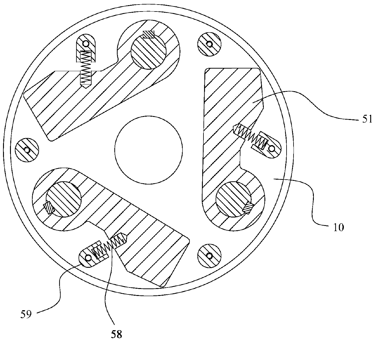
[0042]Further, the cutting mechanism includes: at least two cutting sub-mechanisms; each cutting sub-mechanism is evenly distributed on the rotary disk; Rotary shaft; the cutter is located at one end of the rotary shaft through a connecting assembly; the counterweight is located at the other end of the rotary shaft, and is located on the rotary disc through an elastic limit assembly; when the rotary disc When rotating, each counterweight is adapted to be thrown out of the rotary disc under the action of centrifugal force, and drives the corresponding rotary shaf...


PUM


Abstract

The invention relates to a pipe body cutting device and a working method of the pipe body cutting device. The pipe body cutting device comprises a rotary disc, a cutting mechanism located on the rotary disc and a driving mechanism. A through hole is formed in the center of the rotary disc for penetrating of the pipe body, and the driving mechanism is suitable for driving the rotary disc to rotate so as to drive the cutting mechanism to rotate so as to cut the pipe body. The pipe body cutting device is suitable for cutting aluminum pipes or copper pipes, the pipe body is cut from at least two directions by arranging at least two cutting sub mechanisms, deformation caused by bending of the pipe body in the cutting process is avoided, and outward flash is avoided, so that the cutting quality is good, and the cutting efficiency is high.

Description

technical field [0001] The invention belongs to the technical field of cutting aluminum and copper pipes, and in particular relates to a pipe body cutting device and a working method thereof. Background technique [0002] Extrusion is generally used for the preliminary forming of aluminum and copper tubes. The aluminum or copper material is heated to a certain temperature by a special extruder, and then extruded into the required tubular output through a mold. After the tube reaches a certain length, it needs to be cut off. Since the extruded pipe is still in a high temperature state and is relatively soft, it is easy to bend when cutting in one direction with a traditional saw blade, and the incision will also form a large flash to one side, which will affect the quality, and it is necessary to increase the flash removal process. Contents of the invention [0003] The object of the present invention is to provide a pipe body cutting device and its working method. [0004...

Claims


Application Information

Patent Timeline
IPC IPC(8): B23D21/00B23D21/04
CPCB23D21/003B23D21/04
Inventor 沈建明吴萍
Owner CHANGZHOU INST OF LIGHT IND TECH
Why Eureka
Try Eureka