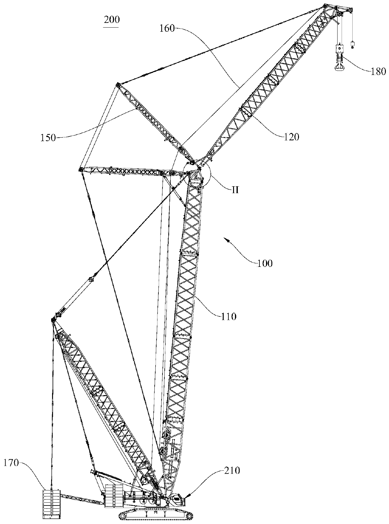
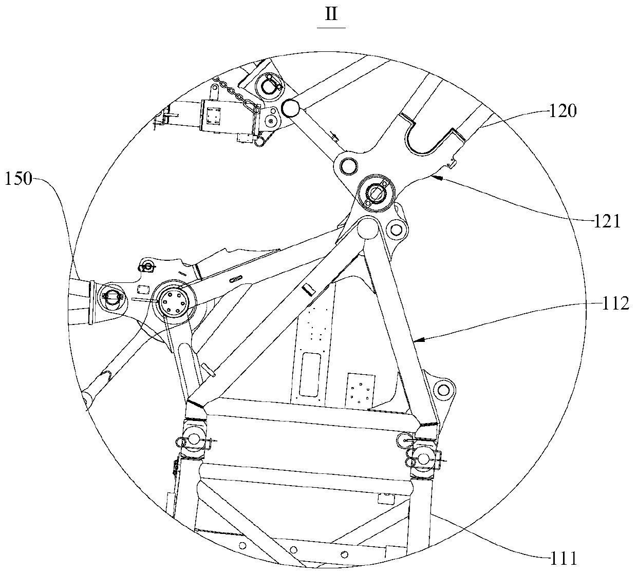
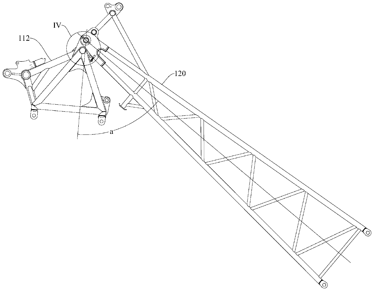
Crane boom and crane

A crane and boom technology, applied in the field of crane booms and cranes, can solve the problems of time-consuming and labor-intensive, easily damaged connecting parts, etc., and achieve the effect of saving labor costs

Pending Publication Date: 2019-09-27
ZHEJIANG SANY EQUIP
View PDF0 Cites 1 Cited by
  • Summary
  • Abstract
  • Description
  • Claims
  • Application Information

AI Technical Summary

Problems solved by technology

However, when the auxiliary arm rotates relative to the main arm, if the angle between the two is too small (less than the extreme angle), it is easy to damage the connection between the two
In the prior art, there is a sensor to detect the angle between the main arm and the auxiliary arm, but the staff need to repeatedly debug the sensor on site to meet the requirements, which is time-consuming and labor-intensive

Method used


Image

  • Crane boom and crane
  • Crane boom and crane
  • Crane boom and crane

Examples


Embodiment Construction

[0028] In order to make the purpose, technical solutions and advantages of the embodiments of the present invention clearer, the technical solutions in the embodiments of the present invention will be clearly and completely described below in conjunction with the drawings in the embodiments of the present invention. Obviously, the described embodiments It is a part of embodiments of the present invention, but not all embodiments. The components of the embodiments of the invention generally described and illustrated in the figures herein may be arranged and designed in a variety of different configurations.

[0029] Accordingly, the following detailed description of the embodiments of the invention provided in the accompanying drawings is not intended to limit the scope of the claimed invention, but merely represents selected embodiments of the invention. Based on the embodiments of the present invention, all other embodiments obtained by persons of ordinary skill in the art wi...


PUM


Abstract

The invention provides a crane boom and a crane and relates to the technical field of engineering equipment. The crane boom comprises a primary arm and a secondary arm rotataly connected onto the primary arm, wherein one of the primary arm or secondary arm is provided with a sensor; the other of the primary arm or secondary arm is provided with a triggering piece; the sensor and the triggering piece are fixedly connected with a circular hole in the crane boom; and when the included angle between the primary arm and the secondary arm reaches a preset extreme position included angle, the triggering piece can trigger the sensor. The crane boom can timely feed back relevant information when the included angle between the primary arm and the secondary arm reaches the preset extreme position included angle. As the triggering piece and the sensor are fixed through the circular hole, the situation that a working staff repeatedly debugs the positions of the sensor and the triggering piece on site is avoided, and both time and labor are saved. The crane comprises the crane boom; and as the positions of the sensor for feeding back the included angle of the primary arm and the secondary arm and the triggering piece do not need to be repeatedly adjusted, the crane has the advantage of saving labor cost and time cost.

Description

technical field [0001] The invention relates to the field of engineering machinery, in particular to a crane jib and a crane. Background technique [0002] Existing cranes often include a main arm and an auxiliary arm, the main arm can rotate relative to the main body of the crane, and the auxiliary arm can rotate relative to the main arm. However, when the auxiliary arm rotates relative to the main arm, if the angle between the two is too small (less than the extreme angle), it is easy to damage the connection between the two. In the prior art, there is a sensor to detect the angle between the main arm and the auxiliary arm, but the staff need to repeatedly debug the sensor on site to meet the requirements, which is time-consuming and labor-intensive. Contents of the invention [0003] The purpose of the present invention includes, for example, providing a jib frame and a crane, which can reduce a large number of on-site debugging steps for workers, saving time and effor...

Claims


Application Information

Patent Timeline
Patent Type & Authority Applications(China)
IPC IPC(8): B66C23/68B66C23/60
CPCB66C23/60B66C23/68
Inventor 沈明张扬黄彬
Owner ZHEJIANG SANY EQUIP
Why Eureka
Try Eureka