Novel self-lubricating gear

A self-lubricating, gear technology, applied in the direction of gear lubrication/cooling, belt/chain/gear, components with teeth, etc., can solve problems such as insufficient lubrication, affecting work efficiency, and inconvenient operation of artificially lubricated gear meshing parts. Achieve the effect of automatic lubrication avoidance

Inactive Publication Date: 2019-09-27
QINGDAO TECHNOLOGICAL UNIVERSITY
View PDF5 Cites 4 Cited by
  • Summary
  • Abstract
  • Description
  • Claims
  • Application Information

AI Technical Summary

Problems solved by technology

[0004] Aiming at the above-mentioned deficiencies in the prior art, the present invention provides a new type of self-lubricating gear, which can realize the automatic lubrication of the gear, and solve the problem that in the prior art, the lack of lubrication in the working process of the gear affects the working efficiency and the life of the gear, and the operation of the meshing part of the artificially lubricated gear Inconvenient question

Method used


Image

  • Novel self-lubricating gear
  • Novel self-lubricating gear
  • Novel self-lubricating gear

Examples


Embodiment Construction

[0018] The specific implementation manner of the present invention will be further described below in conjunction with the accompanying drawings. Wherein the same components are denoted by the same reference numerals. It should be noted that the words "front", "rear", "left", "right", "upper" and "lower" used in the following description refer to the directions in the drawings, and the words "inner" and "outer ” refer to directions towards or away from the geometric center of a particular part, respectively.

[0019] In order to make the content of the present invention more clearly understood, the technical solutions in the embodiments of the present invention will be clearly and completely described below in conjunction with the drawings in the embodiments of the present invention.

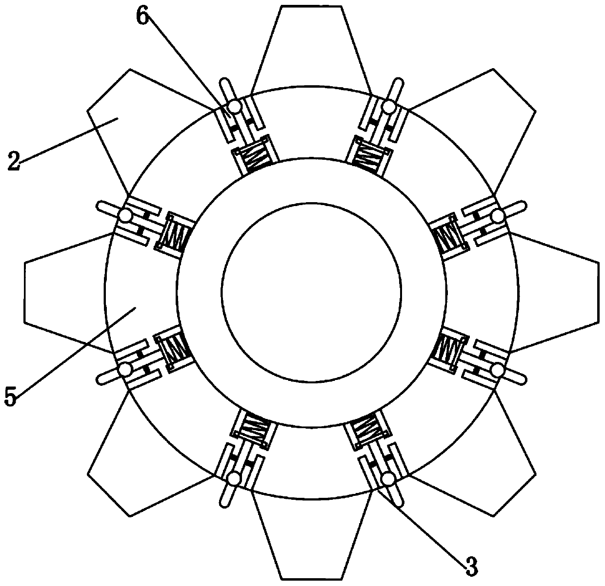
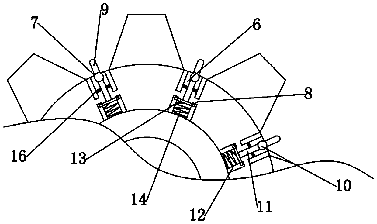
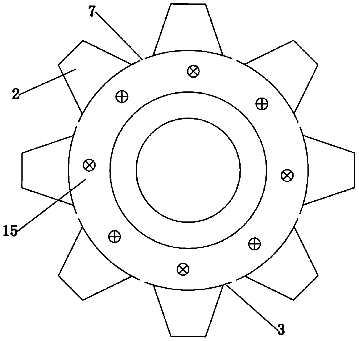
[0020] Such as Figure 1 to Figure 4 A new type of self-lubricating gear is shown, comprising: a gear body 1, gear teeth 2 are uniformly arranged on the outer circumference of the gear body 1,...


PUM


Abstract

The invention discloses a novel self-lubricating gear. The novel self-lubricating gear comprises a gear body, wherein wheel teeth are uniformly arranged on the outer circumference of the gear body, tooth grooves are formed between the wheel teeth, an oil injection hole is formed in one side surface of the gear body, and an oil storage cavity is formed in the other side surface of the gear body; an upper oil outlet hole is formed in the middle of each tooth groove, oil storage columns with the same length as the tooth grooves are arranged on the inner side of the oil storage cavity, springs are fixedly connected to the interiors of the oil storage columns and the inner wall of the bottom end of the oil storage cavity, and inner oil outlet holes are formed in the two sides of the lower part of each oil storage column; and a sliding block is adapted to the inner side of each sliding groove, the other end of the each spring is connected below the corresponding sliding block, a lower pressing rod is fixedly connected above each sliding block, a rolling ball for blocking the corresponding upper oil outlet hole is fixedly connected to the top end of each lower pressing rod, and an upper pressing rod which is arranged on the outer side of the each upper oil outlet hole is fixedly connected to the top end of the corresponding rolling ball. Automatic lubricating of the gear can be realized, and the problems that in the prior art, the working efficiency and the service life of the gear are influenced due to the fact that lubricating in the gear working process is not in place and the operation is inconvenient when a gear meshing part is lubricated manually can be solved.

Description

technical field [0001] The invention relates to the technical field of mechanical transmission, in particular to a novel self-lubricating gear. Background technique [0002] As a common power transmission component, a gear is generally matched with a paired gear or rack to achieve the transmission function. The gear will be subjected to a large mechanical friction force during the meshing transmission process, and this friction force has a great influence on the transmission effect of the gear. , and long-term friction will cause great wear or damage to the gear, affecting the service life of the gear. [0003] This requires continuous lubrication of the meshing parts of the gears during the working process to improve the working conditions of the gears. At this stage, the meshing parts of the gears are mainly lubricated by artificially adding lubricating oil. On the one hand, this method requires shutdown lubrication and will affect the work. efficiency, on the other hand,...

Claims


Application Information

Patent Timeline
IPC IPC(8): F16H55/17F16H55/14F16H57/04
CPCF16H55/14F16H55/17F16H57/0431
Inventor 李杨任付娥李征王彤高远
Owner QINGDAO TECHNOLOGICAL UNIVERSITY
Why Eureka
Try Eureka