Control device and control method for achieving C arm system follow-up motion

A control device and control method technology, applied in the field of medical equipment, can solve the problems of other joints that cannot be controlled, large-stroke operation is unfavorable for doctors to operate, and cumbersome operating procedures, so as to save time required for positioning, avoid inconvenient operation, and simple operation convenient effect

Active Publication Date: 2013-10-09
SHENZHEN INST OF ADVANCED TECH CHINESE ACAD OF SCI
View PDF6 Cites 11 Cited by
  • Summary
  • Abstract
  • Description
  • Claims
  • Application Information

AI Technical Summary

Problems solved by technology

However, this X-ray device is only for single-axis motion, and is only limited to the sliding of the C-shaped part, and cannot control other joints; and the separation of the operating device and the switch results in cumbersome operating procedures, and the operating device is installed on the C-shaped part. The resulting large stroke operation is not conducive to the convenient operation of doctors

Method used


Image

  • Control device and control method for achieving C arm system follow-up motion
  • Control device and control method for achieving C arm system follow-up motion
  • Control device and control method for achieving C arm system follow-up motion

Examples


Embodiment 1

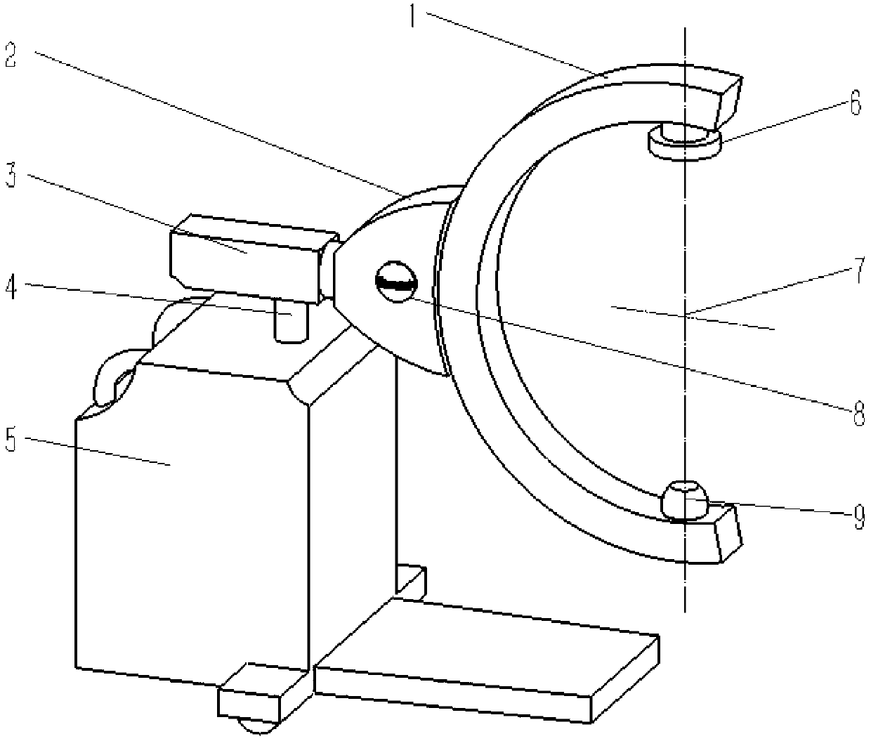
[0042] Embodiment 1. The embodiment of the present invention provides a control device for realizing the follow-up motion of the C-arm system, including an active drive element, an auxiliary control handle, an infrared switch and a force sensor. Each joint of the C-arm system is equipped with an active drive component, the auxiliary control handle is connected with the C-arm system through the force sensor, and the auxiliary control handle is provided with an infrared switch. In the open state, the force sensor obtains the operation intention and transmits the instruction to each joint The active drive element drives each joint of the C-arm system to move.

[0043] see figure 1 , in this embodiment, the structure of the C-arm system consists of four parts, including: X-ray system, C-arm (1), support arm (2), mobile frame (3) and lifting frame (5), the The X-ray system includes an X-ray light source (9) fixed at both ends of the C-arm (1) and an image detection device (6). The...

Embodiment 2

[0058] Example 2, please refer to Figure 5 , an embodiment of the present invention provides a control method for realizing the follow-up motion of a C-arm system, including the following steps:

[0059] (1) Control state detection: detect the infrared switch state of the auxiliary control handle. When the auxiliary control handle is not held, the infrared switch signal is 0, the follow-up motion function is turned off, and the system does not respond to the force sensor signal. C The arm system remains stationary, when the auxiliary control handle is held, the infrared switch signal becomes 1, the follow-up motion function is turned on, and the system responds to the force sensor signal;

[0060] Preferably, a period of start-up delay, such as 1 second, is set in the control state detection, that is, the system starts to respond to the force sensor signal after 1 second after the infrared switch is triggered.

[0061] (2) Force sensor signal processing: After filtering high...


PUM


Abstract

The invention discloses a control device for achieving C arm system follow-up motion. The control device comprises active driving elements, an auxiliary control handle, an infrared switch and a force sensor. All joints of a C arm system are provided with the active driving elements, the auxiliary control handle is connected with the C arm system through the force sensor, and the infrared switch is arranged on the auxiliary control handle. In the starting state, the force sensor obtains operating intentions and transmits commands to the active driving elements of all the joints, and the active driving elements drive the joints of the C arm system to move. According to the control device for achieving C arm system follow-up motion, an operator only needs to apply a little force to flexibly and naturally operate a C arm so as to accurately complete expected motion and positioning according to the will of the operator, and therefore intuitive, simple, accurate and efficient operation is achieved.

Description

technical field [0001] The invention relates to the field of medical equipment, in particular to a control device and a control method for realizing the follow-up motion of a C-arm system. Background technique [0002] The C-arm X-ray machine is mainly used for intraoperative X-ray imaging. It is an important tool in clinical treatment such as vascular intervention and spinal surgery. Or real-time update display on intraoperative images, which has very important clinical application value. The function of the C-arm is inseparable from motion and positioning. In many cases, the C-arm is connected to one end of the movable arm. In such cases, the C-arm can typically be raised and lowered, moved from side to side, or rotated about one or more axes of rotation. Thus, such a C-arm can be moved and repositioned to take X-ray images from different positions and angles without requiring patient movement. At present, the main operation methods on the C-arm include active and passi...

Claims


Application Information

Patent Timeline
Patent Type & Authority Applications(China)
IPC IPC(8): A61B6/00
Inventor 熊璟张磊张忠林李志成谢耀钦王磊
Owner SHENZHEN INST OF ADVANCED TECH CHINESE ACAD OF SCI
Why Eureka
Try Eureka