
Sliding plate valve structure

A technology for slide valves and plate valves, applied in slide valves, valve devices, engine components, etc., can solve problems such as fluid leakage and poor durability of slide valves, and achieve low cost, simple and fast installation methods, and convenient installation

Inactive Publication Date: 2019-09-27
CHONGQING CHUANWU INSTR
View PDF6 Cites 2 Cited by
  • Summary
  • Abstract
  • Description
  • Claims
  • Application Information

AI Technical Summary

Problems solved by technology

[0005] However, the disadvantage of the existing technology is that the valve stem and the plate valve core of the slide valve structure in the prior art are fixedly connected by welding, threaded connection or integral molding. This connection method has a big disadvantage: the plate valve core. The valve core should often frictionally slide against the plate valve seat to control the circulation or cut-off of the fluid. Over time, due to the influence of friction, the plate valve core and the plate valve seat will be thinned by friction, so that there will be a gap between the plate valve core and the plate valve seat. A certain gap is formed, and the fluid will leak from the gap, resulting in the common bad phenomenon that the durability of the slide valve is not strong.

Method used


Image

  • Sliding plate valve structure
  • Sliding plate valve structure
  • Sliding plate valve structure

Examples


Embodiment Construction

[0034] The preferred embodiments of the present invention will be described in detail below in conjunction with the accompanying drawings, so that the advantages and features of the present invention can be more easily understood by those skilled in the art, so as to define the protection scope of the present invention more clearly. Based on the embodiments of the present invention, all other embodiments obtained by persons of ordinary skill in the art without making creative efforts belong to the protection scope of the present invention.

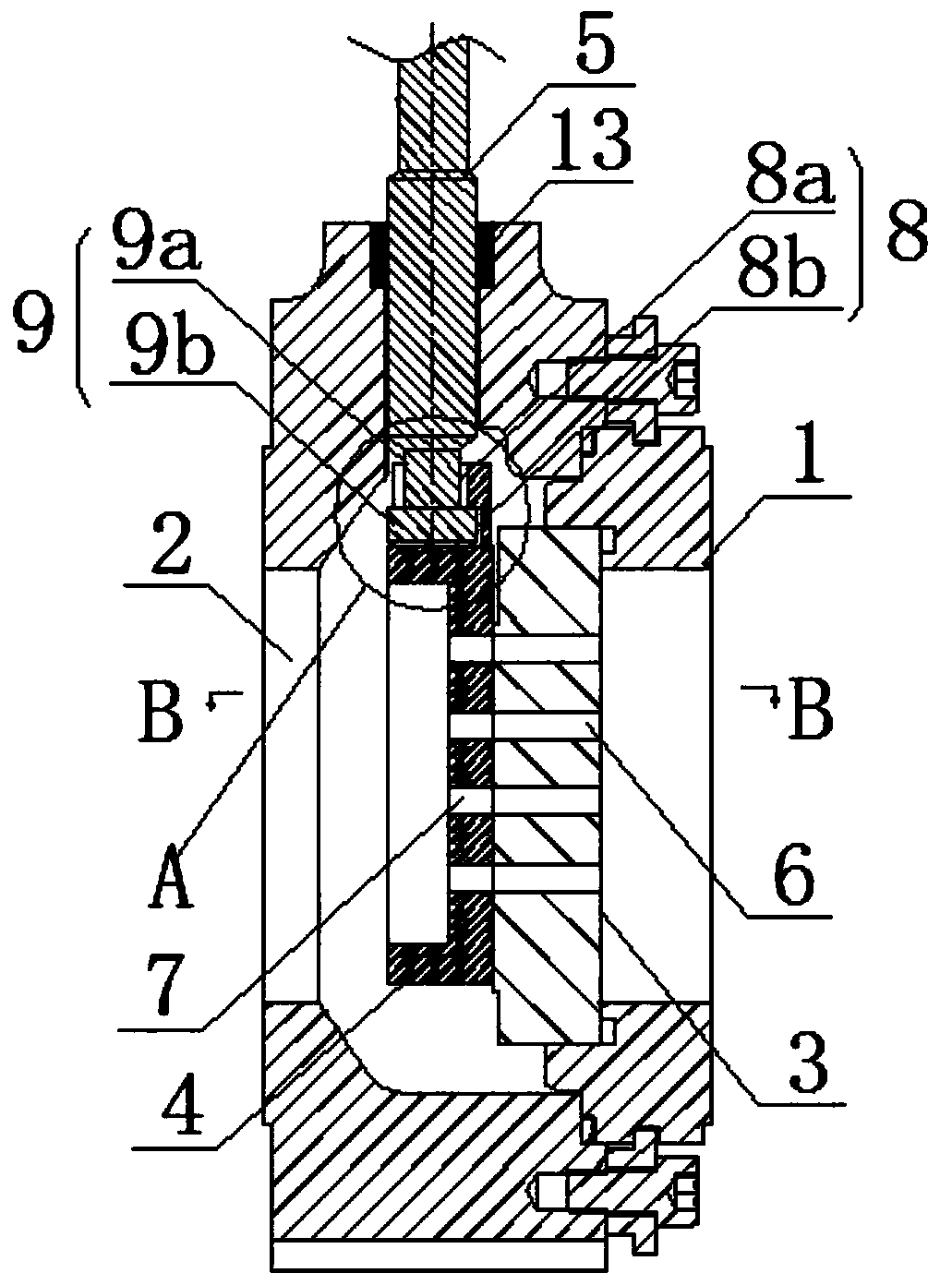
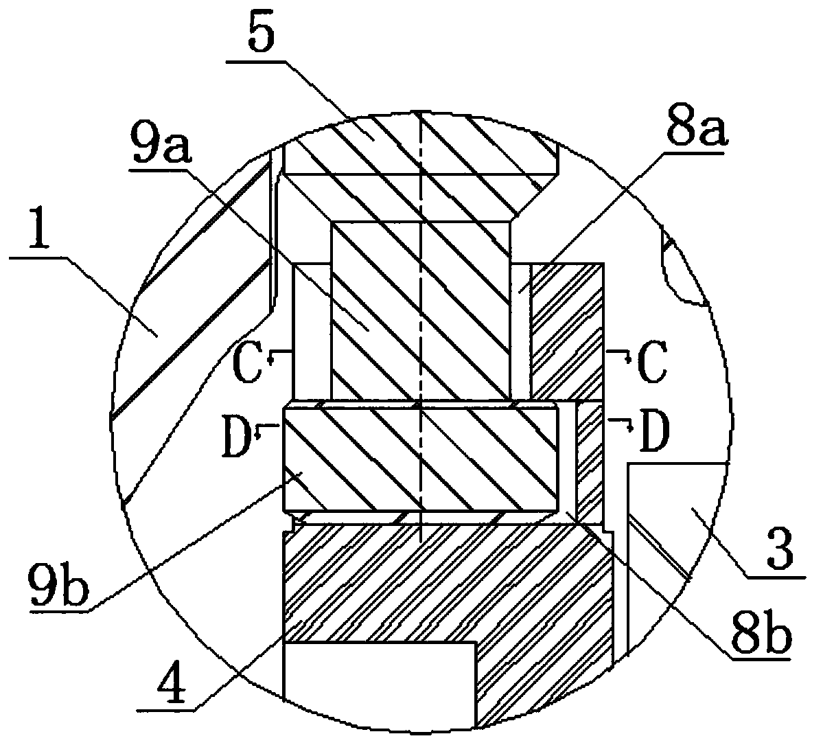
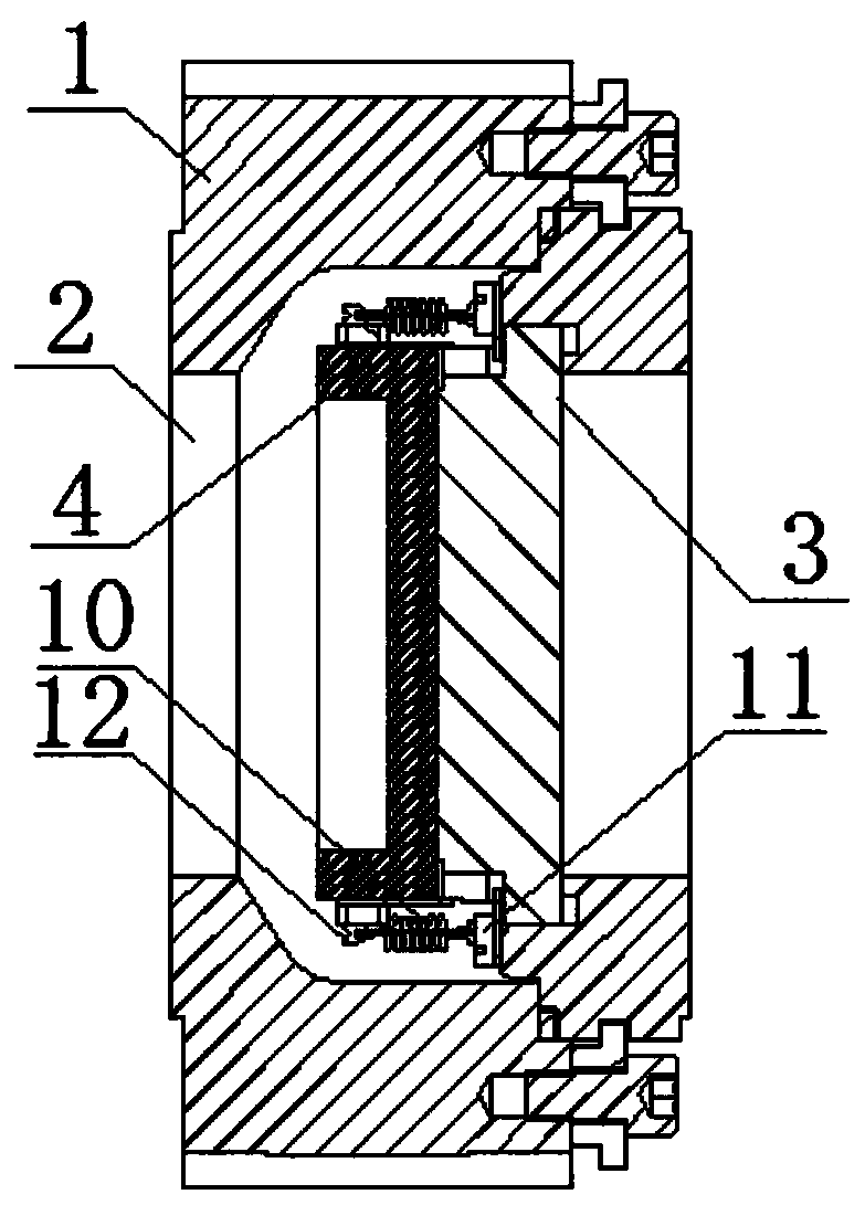
[0035] like Figure 1-Figure 3Shown: a slide valve structure, which is composed of a valve body 1, a flow channel 2, a plate valve seat 3, a plate valve core 4 and a valve stem 5, the flow channel 2 is arranged transversely and runs through the valve body 1, the The valve seat 3 is set in the flow channel 2 and is perpendicular to the flow direction of the medium. The edge of the valve seat 3 is sealed with the inner wall of the flow chann...


PUM


Abstract

The invention provides a sliding plate valve structure which is provided for mainly solving that fluid medium leakage is caused easily by sliding friction between a plate valve element and a plate valve seat when a sliding plate valve is in use in the prior art. The sliding valve structure comprises a valve body, a flow channel, a plate valve seat, a plate valve element and a valve rod. The flow channel is transversely arranged and penetrates through the valve body. First via holes are distributed on the valve seat. The plate surface of the valve element is closely attached to the valve seat. Second via holes are distributed on the valve element. The valve rod drives the valve element to slide and be locked in the axial direction of the valve rod. The top of the valve element is provided with a limiting sliding groove. The limiting sliding groove is formed in the radial direction of the valve rod. The limiting sliding groove is perpendicular to the plate surface of the valve seat. A connecting block is arranged in the limiting sliding groove. The connecting block is fixedly connected with the bottom end of the valve rod. The connecting block is slidably connected with the limiting sliding groove. The connecting block is limited in the limiting sliding groove in the axial direction of the valve rod. The sliding plate valve structure is mainly used for connection of the valve rod and the valve element in the sliding plate valve structure.

Description

technical field [0001] The invention relates to the technical field of valves, in particular to a slide valve structure capable of making up for the grinding loss of the slide valve. Background technique [0002] As a control element to control the flow direction of gas or liquid flowmeters, valves have been widely used in production and life. With the development of science and technology, valves are used in more and more technical fields, and they play more and more roles in production and life. more important. [0003] In recent years, in the field of valve technology, there have been more valves that use a plate structure as a valve core, and use a plate structure valve seat to cooperate with a plate structure valve core to control the flow of gas or liquid. We call it a slide valve. . The traditional valve structure takes a butterfly valve as an example. The fluid medium will generate a large fluid pressure on the valve disc. When the fluid needs to be shut off, a con...

Claims


Application Information

Patent Timeline
Patent Type & Authority Applications(China)
IPC IPC(8): F16K3/02F16K3/30
CPCF16K3/0281F16K3/30
Inventor 晏行鲜代兴肖亮
Owner CHONGQING CHUANWU INSTR
Learn More