Golf club shaft having wave shaped reinforced part and making method thereof

A golf ball and wave-shaped technology, applied to golf balls, golf clubs, rackets, etc., can solve the problems of reduced flexural strength, complicated manufacturing process, increased flight distance, etc., and achieve the effect of improving twist characteristics

Inactive Publication Date: 2003-03-12
韦弗克斯公司
View PDF0 Cites 1 Cited by
  • Summary
  • Abstract
  • Description
  • Claims
  • Application Information

AI Technical Summary

Problems solved by technology

Inaccurate ball flight distance when the ball is hit by an area other than the midpoint of the face of the clubhead
[0004] According to the traditional method of improving the torsion characteristics of rods, first, the fiber orientation of the twisted layer (the angle formed by the rod axis and the carbon fiber texture in the prepreg sheet) should be ±45°, and the prepreg sheet is used for rolls. Winding the rod several times; however, the disadvantage of this method is that the flexural strength is significantly reduced and the weight of the rod increases, although the torsional characteristics are improved
[0005] Second, steel or aluminum alloy is installed inside

Method used


Image

  • Golf club shaft having wave shaped reinforced part and making method thereof
  • Golf club shaft having wave shaped reinforced part and making method thereof
  • Golf club shaft having wave shaped reinforced part and making method thereof

Examples


Embodiment Construction

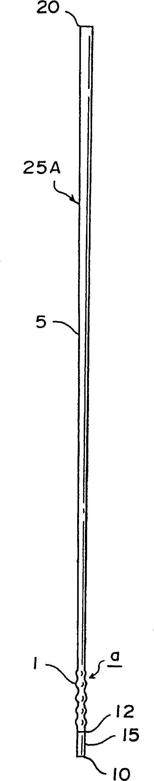
[0032] figure 1 A first embodiment of the golf club shaft 25A of the present invention is shown in which the wave-shaped reinforcing portion 1 is formed at the lower portion of the golf club shaft. The lower part of the rod is located between the midpoint of the entire length of the rod and the upper end 12 of the sleeve part. figure 1 A preferred position a of the reinforcement close to the sleeve part 15 is shown. Of course, the corrugated part 1 can be located at other positions between the upper end of the sleeve part and the midpoint of the lower part of the rod. When the wave-shaped reinforcing part 1 is located at the position a of the base shaft 5, the flexing characteristics of the golf club shaft are significantly improved.

[0033] The wave-shaped reinforced portion of the golf club shaft of the present invention is composed of reinforced segments. In the wave-shaped reinforced part 1, the number of reinforcing segments is 1-6 segments, preferably 1-3 segments. ...


PUM

PropertyMeasurementUnit
Lengthaaaaaaaaaa

Abstract

The present invention relates to a golf club shaft 25B having improved torsion characteristics comprising a base shaft 5 having an internal surface and an external surface, and at least one wave shaped reinforced part 30 on at least one of said surfaces, said wave shaped reinforced part 30 comprising a plurality of reinforcement pieces. The wave shaped reinforced part 30 is located on at least one of the upper portion, midpoint or lower portion. The golf club shafts of the present invention can be made by applying a base section 2B of a prepreg sheet 2A or assembly having a plurality of finger like elements 2 to a portion of a base shaft 5, wrapping the finger like elements 2 around the base shaft 5 to provide a wave shaped reinforced part 30 having a plurality of reinforcement pieces, and curing the shaft having the wave shaped reinforced part 30 thereon to produce a golf club shaft 25B having a wave shaped reinforced part 30.

Description

[0001] This application is a continuation-in-part of Serial No. 29 / 061700, filed October 29, 1996, and Serial No. 08 / 760079, filed December 4, 1996. This application claims the benefit of US Provisional Application No. 60 / 047697, filed May 23,1997. technical field [0002] The present invention relates to a golf club shaft, in particular, to a golf club shaft having a corrugated reinforcement, and to a method of manufacturing the golf club shaft. Background technique [0003] Since the carbon (graphite) shaft is lighter than the conventional steel shaft, the head speed of the golf club increases during the swing, thereby increasing the flight distance of the ball hit by the golf club. However, graphite shafts have a disadvantage in that they have poor torsion characteristics. If the twist characteristics of the club shaft are poor, the midpoint of the ball striking face of the club head generally does not touch the ball during...

Claims


Application Information

Patent Timeline
IPC IPC(8): A63B53/10A63B53/12
CPCA63B59/0025A63B53/10A63B2209/023A63B59/0014A63B59/0077A63B53/12A63B60/06A63B60/08A63B60/10A63B60/12A63B60/48
Inventor 柳皙淏
Owner 韦弗克斯公司
Why Eureka
Try Eureka