Two-dimensional airfoil profile mean mean camber line numerical calculation method

A numerical calculation and two-dimensional airfoil technology, applied in the field of geometric modeling, can solve problems such as complex calculations and difficulty in application, and achieve fast convergence, applicable boundaries, and easy-to-understand and use effects

Active Publication Date: 2019-09-27
SHANGHAI JIAO TONG UNIV
View PDF3 Cites 0 Cited by
  • Summary
  • Abstract
  • Description
  • Claims
  • Application Information

AI Technical Summary

Problems solved by technology

The above two types of methods have certain advantages in specific application environments in the literature, but there are also some defects, such as complex calculations, difficult to apply at the intersection of leading edge and trailing edge, and need to rely on computational modeling provided by large commercial software such as UG Function etc.

Method used


Image

  • Two-dimensional airfoil profile mean mean camber line numerical calculation method
  • Two-dimensional airfoil profile mean mean camber line numerical calculation method
  • Two-dimensional airfoil profile mean mean camber line numerical calculation method

Examples


Embodiment Construction

[0050] The following describes several preferred embodiments of the present invention with reference to the accompanying drawings, so as to make the technical content clearer and easier to understand. The present invention can be embodied in many different forms of embodiments, and the protection scope of the present invention is not limited to the embodiments mentioned herein.

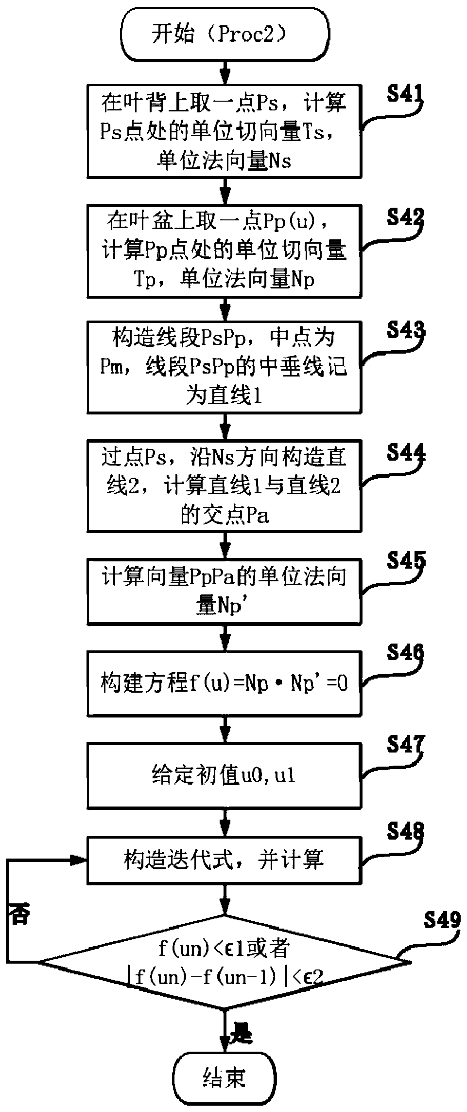
[0051] The present invention is realized through the following technical steps, which can be summarized into two processes, the overall process is represented by Proc1, and the core sub-process of Proc1 is represented by Proc2.

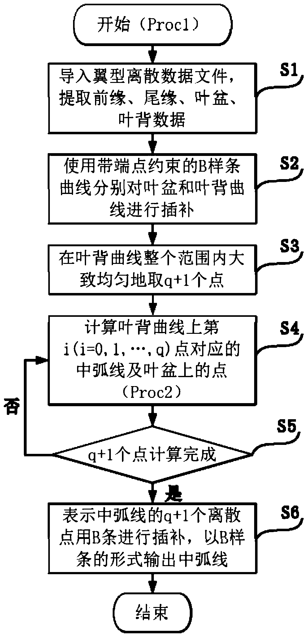
[0052] Such as figure 1 As shown, the overall process Proc1 specifically includes:

[0053] Step S1, import the airfoil discrete data file (NACA9124), and extract the data of leading edge, trailing edge, blade pot and blade back. An example of a data file is as follows:

[0054]

[0055] #Discrete point coordinates of leaf basin (Xp, Yp), discrete point coordinates of ...


PUM


Abstract

The invention discloses a two-dimensional airfoil profile mean camber line numerical calculation method, and relates to the technical field of geometric modeling. The method comprises the following steps of importing an airfoil profile discrete data file, and extracting the front edge, tail edge, blade basin and blade back data; performing interpolation on a blade basin curve and a blade back curve by using a B spline curve with the end point constraint; uniformly taking N points in the whole range of the blade back curve; calculating the middle arc lines corresponding to N points on the blade back curve and the points on the blade basin; and interpolating N discrete points representing the mean camber line by using the B spline, and outputting the mean camber line in the form of the B spline. The method is clear in geometrical significance and is easy to understand and use, does not need a large-scale commercial CAD modeling software, and has the characteristics of high precision, high convergence speed, applicable boundary and the like.

Description

technical field [0001] The invention relates to the technical field of geometric modeling, in particular to a numerical calculation method for a two-dimensional airfoil mid-arc. Background technique [0002] The two-dimensional cross-section airfoil is generally composed of four sections, which are leading edge 1, trailing edge 2, blade basin 3 (or pressure surface), and blade back 4 (or suction surface). A series of inscribed circles 5 can be constructed inside the two-dimensional airfoil, and the line connecting the centers of these inscribed circles constitutes the central arc 6, such as image 3 shown. [0003] The mid-arc is one of the important benchmarks of airfoil design, and it is also the basis for the dispersion of section lines. It has a very important impact on the quality of blades, wings, etc., and a small error in the mid-arc may lead to the final airfoil profile. Smoothness affects the aerodynamic performance of blades, wings and other components. [0004]...

Claims


Application Information

Patent Timeline
Patent Type & Authority Applications(China)
IPC IPC(8): G06F17/50
CPCG06F30/20
Inventor 姜振华王成恩
Owner SHANGHAI JIAO TONG UNIV
Why Eureka
Try Eureka