
A Simulation Method of Dam Abutment Deformation Based on Body Force Application
A body force and abutment technology, applied in instrumentation, geometric CAD, design optimization/simulation, etc., can solve problems such as inconsistent deformation laws, large deformation in the deep part of the abutment rock mass, and small deformation in the shallow part
- Summary
- Abstract
- Description
- Claims
- Application Information
AI Technical Summary
Problems solved by technology
Method used
Image

Examples
Embodiment
[0050] An arch dam with a dam height of 305m is located in the southwest of my country. The geological conditions on the left bank are average. During the construction and operation, horizontal deformation will occur, which will affect the working performance of the dam. It is necessary to investigate the influence of the deformation of the left bank abutment on the working performance of the dam. analyze.
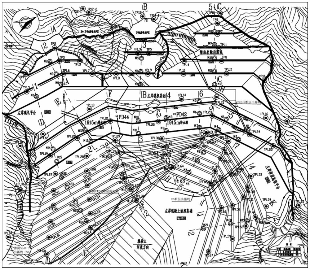
[0051] Step 1: Set the horizontal deformation measuring point grid according to the topographic and geological conditions of the left bank, such as figure 2 , the specific measuring point location is as figure 2 shown;
[0052]Step 2: Obtain the deformation value by monitoring, the representative monitoring value is shown in Table 1, and the monitoring frequency is 1 time / month;
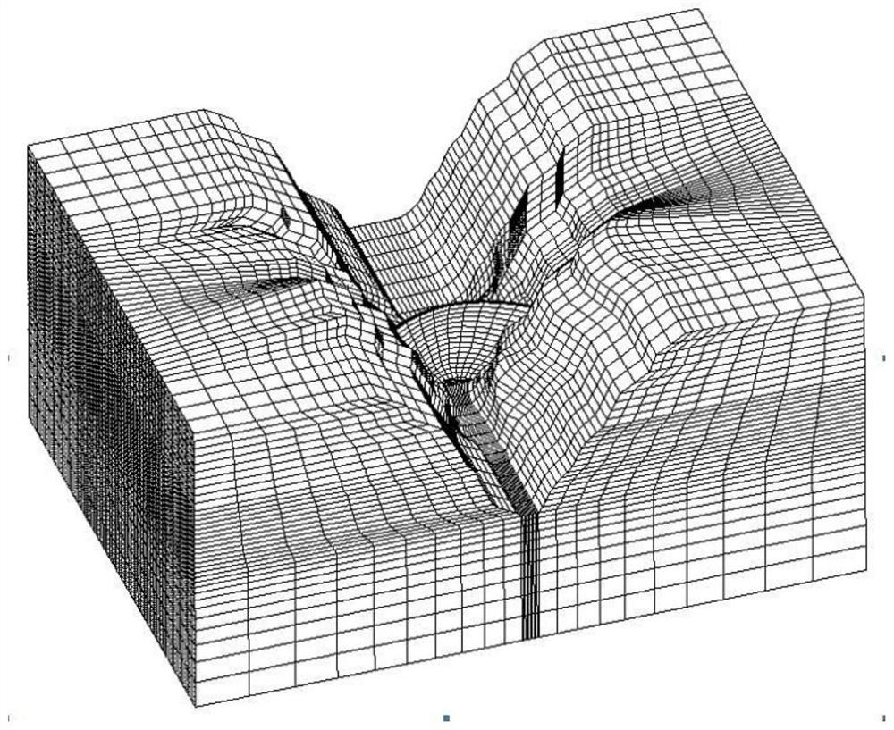
[0053] Step 3: Carry out regional division according to topographic and geological conditions, etc., a total of 6 regions, and establish a finite element grid such as image 3 ;
[0054] Ste...
PUM
 Abstract
Description
Claims
Application Information