
Method for adjusting upper limit of shutter of camera, computer readable storage medium and camera

A computer program and camera technology, applied to computer-readable storage media and cameras, to adjust the upper limit of the shutter of the camera, which can solve problems such as inconvenient use and poor user experience, and achieve the effects of convenient use, improved image quality, and reduced noise

Inactive Publication Date: 2019-09-27
SHENZHEN ARASHI VISION CO LTD
View PDF5 Cites 2 Cited by
  • Summary
  • Abstract
  • Description
  • Claims
  • Application Information

AI Technical Summary

Problems solved by technology

[0003] The object of the present invention is to provide a method for adjusting the shutter upper limit of a camera, a computer-readable storage medium and a camera, aiming at solving the problem that people can only shoot by constantly adjusting the upper limit of the shutter of the camera so that no matter it is a moving scene or a static scene. High-quality images, very inconvenient to use, poor user experience

Method used


Image

  • Method for adjusting upper limit of shutter of camera, computer readable storage medium and camera
  • Method for adjusting upper limit of shutter of camera, computer readable storage medium and camera

Examples


Embodiment 1

[0015] see figure 1 The method for adjusting the shutter upper limit of the camera provided by Embodiment 1 of the present invention includes the following steps:

[0016] S101. Determine the motion state of the camera according to the gyroscope data or according to the movement of the feature points of the stationary objects in multiple frames of adjacent images.

[0017] In Embodiment 1 of the present invention, judging the motion state of the camera according to the gyroscope data may specifically include the following steps:

[0018] Obtain the data of the inertial measurement unit (Inertial measurement unit, IMU) sensor, the data includes 3-axis gyroscope data and 3-axis accelerometer data;

[0019] Calculate the variance of the 3-axis accelerometer data at a fixed frequency (such as 300ms), and find the maximum value of the 3-axis gyroscope data;

[0020] Judging whether the variance of the 3-axis accelerometer data and the maximum value of the 3-axis gyroscope data ar...

Embodiment 2

[0034] Embodiment 2 of the present invention provides a computer-readable storage medium, the computer-readable storage medium stores a computer program, and when the computer program is executed by a processor, the adjustment of the shutter upper limit of the camera as provided in Embodiment 1 of the present invention is implemented. steps of the method.

Embodiment 3

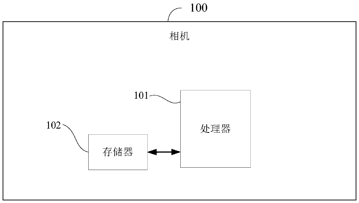
[0036] figure 2 A specific structural block diagram of the camera provided by Embodiment 3 of the present invention is shown. A camera 100 includes: one or more processors 101, memory 102, and one or more computer programs, wherein the processor 101 and the The memory 102 is connected by a bus, the one or more computer programs are stored in the memory 102, and configured to be executed by the one or more processors 101, when the processor 101 executes the computer program The steps of the method for adjusting the shutter upper limit of a camera as provided in Embodiment 1 of the present invention are realized.

[0037] In the present invention, since the motion state of the camera is judged according to the gyroscope data or the movement of the feature points of the stationary objects in multiple frames of adjacent images, the shutter upper limit of the camera is adjusted in real time according to the motion state of the camera. Therefore, shorter shutter speeds and higher ...


PUM


Abstract

The invention is applicable to the field of cameras, and provides a method for adjusting the upper limit of a shutter of a camera, a computer readable storage medium and the camera. The method comprises the following steps: judging the motion state of a camera according to gyroscope data or the characteristic point movement condition of a static object in a plurality of frames of adjacent images; and adjusting the shutter upper limit of the camera in real time according to the motion state of the camera. According to the invention, the camera can preferentially use a shorter shutter and a higher ISO (International Standardization Organization) when moving, so that a picture is prevented from being blurred due to longer exposure time; and a longer shutter and a lower ISO are preferentially used in a static state, so that the noise caused by high ISO is reduced, and the image quality is improved. The use is very convenient and the user experience is good.

Description

technical field [0001] The invention belongs to the field of cameras, and in particular relates to a method for adjusting the upper limit of the shutter of the camera, a computer-readable storage medium and the camera. Background technique [0002] When using a camera to shoot, people generally hope that the blurring of the picture of the moving scene should be reduced as much as possible, and the picture quality of the normal scene should be as high as possible. However, the cameras in the prior art can only simply set shutter priority or ISO (International Standardization Organization, sensitivity) priority. For scenes where continuous short-term motion and short-term stillness appear alternately, people can only shoot high-quality images no matter whether it is a moving scene or a still scene by constantly adjusting the upper limit of the shutter of the camera. Very inconvenient to use and poor user experience. Contents of the invention [0003] The purpose of the pre...

Claims


Application Information

Patent Timeline
Patent Type & Authority Applications(China)
IPC IPC(8): H04N5/232H04N5/235
CPCH04N23/681H04N23/682H04N23/73
Inventor 张明智谭坤郭奕滨
Owner SHENZHEN ARASHI VISION CO LTD
Learn More