Wind power plants with radial turbines and generators

A technology for wind power generation equipment and generators, applied to mechanical equipment, wind engines at right angles to the wind direction, wind engines, etc., to achieve the effects of reducing mechanical transmission losses, increasing application possibilities, and improving efficiency

Inactive Publication Date: 2021-03-16
ウインドクワイエット テクノロジーズ インコーポレーテッド
View PDF10 Cites 0 Cited by
  • Summary
  • Abstract
  • Description
  • Claims
  • Application Information

AI Technical Summary

Problems solved by technology

The other issues above should also be addressed

Method used


Image

  • Wind power plants with radial turbines and generators
  • Wind power plants with radial turbines and generators
  • Wind power plants with radial turbines and generators

Examples


Embodiment Construction

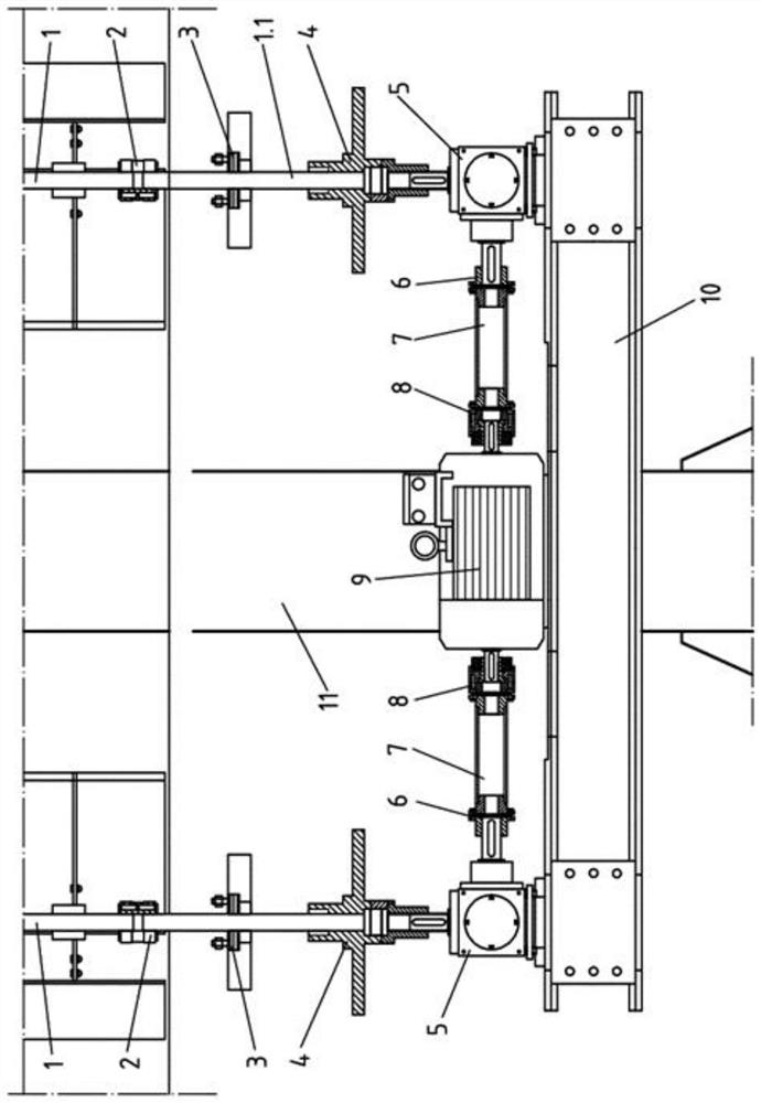
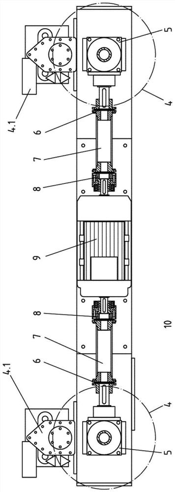
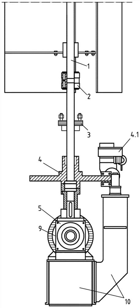
[0030] An upstream energy-generating device (energy source) with two rotor shafts (1) supplies kinetic energy via the coupling (2) via the shafts (1.1) to the drive train. The brake disc (4) with clutch connects the shaft (1.1) to the helical gear (5) which transmits the supplied energy (the transmission ratio is set according to the power design of the generator) and ensures Correct direction of rotation of coupling (6), drive shaft (7), disconnect clutch (8) and generator (9). The generator (9) converts the kinetic energy fed into it into electrical energy.

[0031] In addition, the helical gear (5) is also used for transmission and for reversing the direction of rotation.

[0032] Preferably, instead of a single generator ( 9 ), several generators can also be arranged in the housing, for example in the form of additional winding pairs. In this case, one winding pair can be provided for low power and the other winding pair can be provided for higher power. Up to three win...


PUM


Abstract

The invention relates to a wind power plant with a radial turbine and a generator (9), wherein two radial turbines aligned side by side and parallel are each provided with a vertical rotor shaft (1) which is mutually connected and capable of swinging around a swing axis parallel to the rotor shaft (1), wherein the swing axis and the V-shaped wind distributor are arranged outside the connecting line of the rotor shaft (1), and both Located on the same side of the connecting line, it is characterized in that the same generator (9) can be driven by both rotor shafts (1) via the drive shaft (7). Figure 1 is suggested as an abstract figure.

Description

technical field [0001] The invention relates to a wind power plant with a radial turbine and a generator, wherein two radial turbines are arranged side by side and aligned parallel to one another, each radial turbine has a vertical rotor shaft, the two rotors the shafts are connected to each other and can oscillate about an oscillating axis parallel to said rotor shaft, said oscillating axis and the V-shaped wind distributor being arranged outside and on the same side of the connecting line of the two rotor shafts, The generator is mechanically connected to the rotor shaft through a transmission, and the same generator can be driven by both rotor shafts. Background technique [0002] Such a wind power plant is known from EP2652318B1. Already mentioned here are generators and electromagnetic brakes for the two turbines. [0003] When each radial turbine transfers mechanical energy to a separate generator via a drive belt, the following problems arise: [0004] High power t...

Claims


Application Information

Patent Timeline
Patent Type & Authority Patents(China)
IPC IPC(8): F03D3/02F03D3/04F03D15/00
CPCF03D3/02F03D3/0445F05B2260/4023F05B2260/902F05B2260/903F03D15/00Y02E10/74
Inventor V·纳瓦罗罗梅罗K·泰森
Owner ウインドクワイエット テクノロジーズ インコーポレーテッド
Why Eureka
Try Eureka