Pressure relief and water replenishing valve, and hot water system

A water replenishment valve and pressure relief technology, applied in valve details, multi-way valves, safety valves, etc., can solve problems such as unstable heating pressure, fixed pressure relief parameters of safety valves, high water flow noise, etc.

Pending Publication Date: 2019-10-01
GUANGDONG MACRO GAS APPLIANCE
View PDF0 Cites 1 Cited by
  • Summary
  • Abstract
  • Description
  • Claims
  • Application Information

AI Technical Summary

Problems solved by technology

[0003] For example, the pressure relief parameters of the safety valve of the existing gas heating furnace are fixed, which cannot be changed later, and cannot meet various special use environments, and the applicability is not strong
And most of them use manual water replenishment method, which needs to manually unscrew the water replenishment valve and judge whether the water replenishment is sufficient, and then manually close the water replenishment valve, the whole process is cumbersome
And when the heating water pressure is not enough, the heating furnace will stop running, turn off the heating, and affect the experience
At the same time, the heating pressure will gradually decrease with use, and the end system will have local overheating or local underheating problems. The unstable heating pressure will also easily lead to high water flow noise
[0004] The existing water pipeline needs to be installed in the pressure relief valve and the water supply valve respectively. The more valve bodies, the higher the manufacturing cost, the longer the installation time, and the lower the reliability

Method used


Image

  • Pressure relief and water replenishing valve, and hot water system
  • Pressure relief and water replenishing valve, and hot water system

Examples


Embodiment Construction

[0023] The conception, specific structure and technical effects of the present invention will be clearly and completely described below in conjunction with the embodiments and accompanying drawings, so as to fully understand the purpose, characteristics and effects of the present invention. Obviously, the described embodiments are only some of the embodiments of the present invention, rather than all embodiments. Based on the embodiments of the present invention, those skilled in the art can obtain other embodiments without paying creative work. All belong to the scope of protection of the present invention. In addition, all the connection / connection relationships mentioned in this article do not refer to the direct connection of components, but mean that a better connection structure can be formed by adding or reducing connection accessories according to specific implementation conditions. The various technical features in the invention can be combined interactively on the pr...


PUM


Abstract

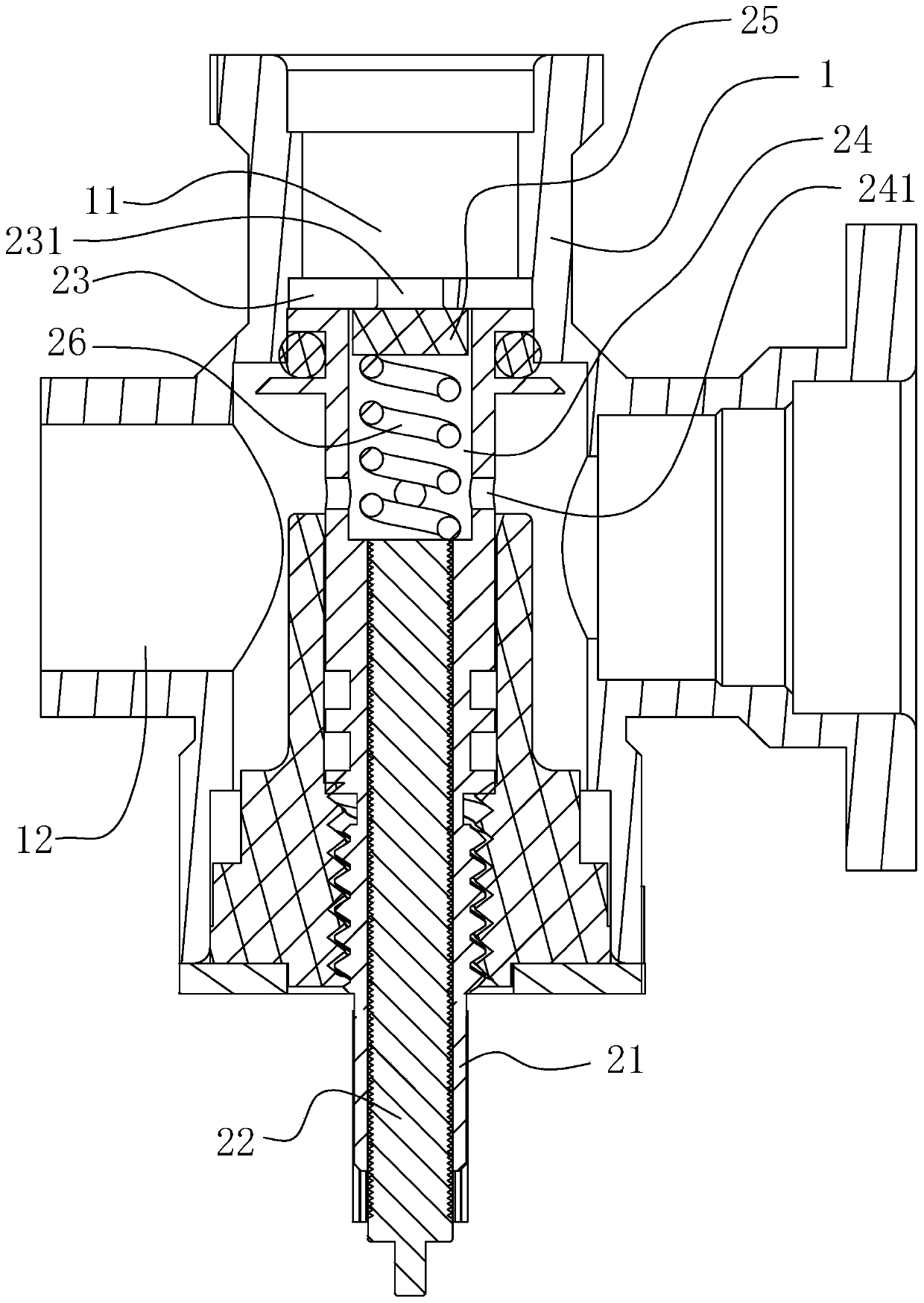
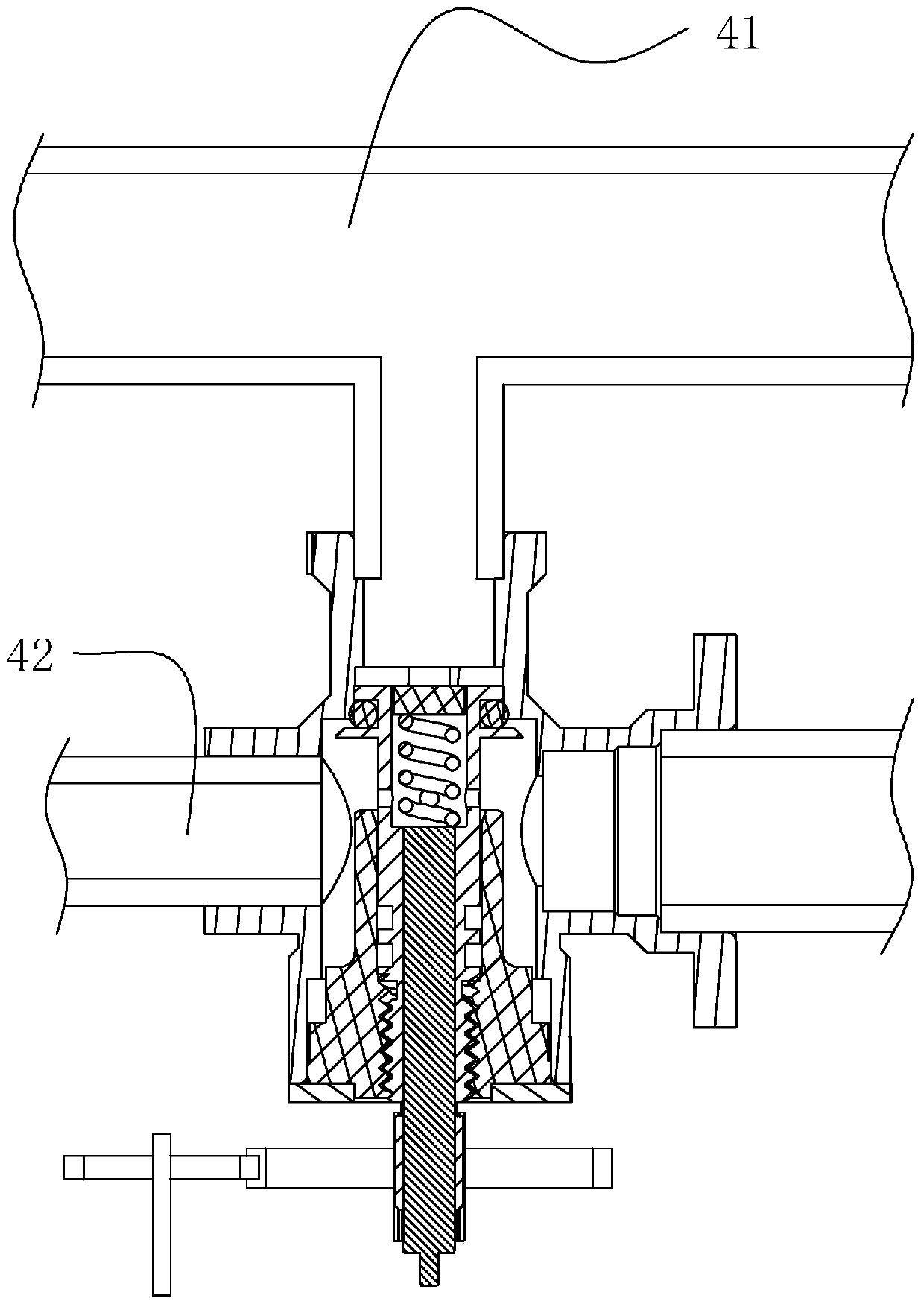
The invention discloses a pressure relief and water replenishing valve. The pressure relief and water replenishing valve comprises a valve body housing, wherein a water replenishing channel and a water supply and overflow channel are formed in the valve body housing, a valve element assembly is arranged on the valve body housing, the valve element assembly comprises a water replenishing port rubber mat and a valve rod, and a pressure relief cavity is formed in the upper end of the valve rod; the pressure relief cavity is provided with an opening, the opening is provided with the water replenishing port rubber mat in a covering manner, a pressure relief rubber mat and a pressure adjustment spring are arranged in the pressure relief cavity, a pressure relief port is formed in the middle partof the water replenishing port rubber mat, an overflow port capable of communicating with the pressure relief port is formed in the pressure relief cavity, and the pressure relief port communicates with the water supply and overflow channel; the pressure adjustment spring is arranged between the pressure relief rubber mat and the bottom of the pressure relief cavity, and the pressure relief rubber mat seals the pressure relief port under the elasticity effect of the pressure adjustment spring, so that the pressure relief port is spaced from the overflow port; and the valve rod is connected with the valve body housing, and is enabled to move up and down on the valve body housing, so that the water replenishing port rubber mat opens and closes the water replenishing channel. A water replenishing pipeline is used for water replenishing; however, the pressure relief port formed in the water replenishing port rubber mat has the function of pressure relief, so that the functions of water replenishing and pressure relief are realized on the same water valve simultaneously.

Description

technical field [0001] The invention relates to the field of water pipeline equipment, in particular to a pressure relief valve and a hot water system. Background technique [0002] In order to ensure water safety, pressure relief valves are often installed, especially for hot water pipelines. In order to avoid damage to water pipes caused by local overheating, it is often necessary to install water replenishment equipment. [0003] For example, the pressure relief parameters of the safety valve of the existing gas heating furnace are fixed and cannot be changed later, which cannot meet various special use environments, and the applicability is not strong. And most of them adopt the manual water supply method, which needs to manually unscrew the water supply valve, and judge whether the water supply is enough, and then need to manually close the water supply valve, and the whole process is cumbersome to operate. And when the heating water pressure is not enough, the heating...

Claims


Application Information

Patent Timeline
Patent Type & Authority Applications(China)
IPC IPC(8): F16K17/06F16K17/04F16K11/10F16K31/04
CPCF16K11/105F16K17/0473F16K17/0486F16K17/06F16K31/04
Inventor 艾穗江祝继祖邓海燕陈仕超
Owner GUANGDONG MACRO GAS APPLIANCE
Why Eureka
Try Eureka