
Azimuth wide-beam synthetic aperture radar imaging method and device

A technology of synthetic aperture radar and imaging method, applied in the field of radar, can solve the problems of image defocusing and image quality degradation, and achieve the effect of precise focusing and improving imaging quality.

Active Publication Date: 2019-10-01
INST OF ELECTRONICS CHINESE ACAD OF SCI
View PDF6 Cites 1 Cited by
  • Summary
  • Abstract
  • Description
  • Claims
  • Application Information

AI Technical Summary

Problems solved by technology

With the increase of the wavelength of the electromagnetic wave used by the synthetic aperture radar, the image quality obtained by this traditional narrow beam approximation processing decreases, and the image is prone to defocusing

Method used


Image

  • Azimuth wide-beam synthetic aperture radar imaging method and device
  • Azimuth wide-beam synthetic aperture radar imaging method and device
  • Azimuth wide-beam synthetic aperture radar imaging method and device

Examples


Embodiment Construction

[0047] In the following description, specific details such as specific system structures and technologies are presented for the purpose of illustration rather than limitation, so as to thoroughly understand the embodiments of the present invention. It will be apparent, however, to one skilled in the art that the invention may be practiced in other embodiments without these specific details. In other instances, detailed descriptions of well-known systems, devices, circuits, and methods are omitted so as not to obscure the description of the present invention with unnecessary detail.

[0048] In order to illustrate the technical solutions of the present invention, specific examples are used below to illustrate.

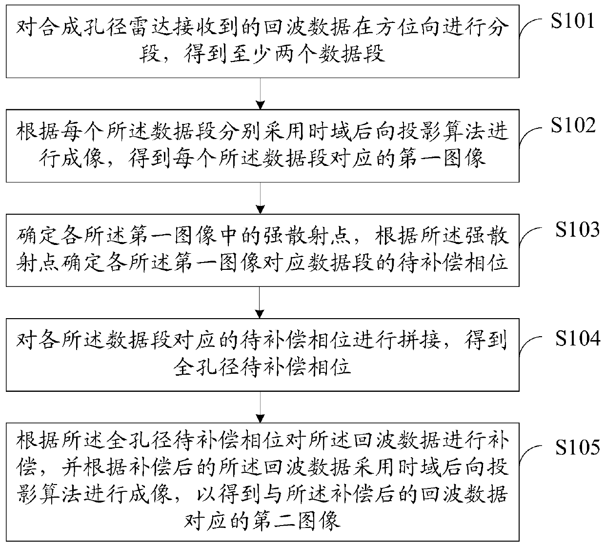
[0049] figure 1 It shows the implementation process of the imaging method of the azimuth wide-beam synthetic aperture radar provided by the embodiment of the present invention, and is described in detail as follows:

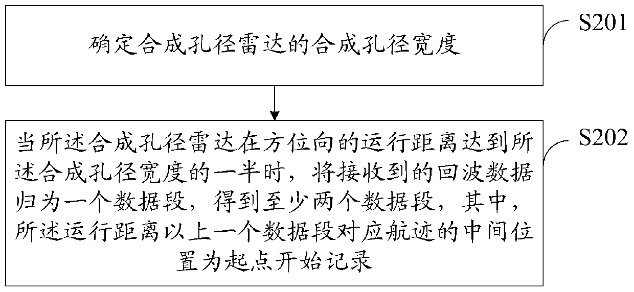
[0050] In S101, the echo data received by the synt...


PUM


Abstract

The invention provides an azimuth wide-beam synthetic aperture radar imaging method and device, and a computer-readable storage medium, wherein the imaging method comprises the steps of: segmenting echo data in the azimuth direction, so that at least two data segments are obtained; according to each data segment, performing imaging by respectively adopting a time-domain backward projection algorithm, so that a first image corresponding to each data segment is obtained; determining strong scattering points in various first images, and determining to-be-compensated phases of data segments corresponding to the various first images; splicing the to-be-compensated phases of the various data segments, so that the full-aperture to-be-compensated phase is obtained; and, compensating the echo dataaccording to the full-aperture to-be-compensated phase, and performing imaging by adopting the time-domain backward projection algorithm according to the compensated echo data, so that a second imagecorresponding to the compensated echo data is obtained. By means of the azimuth wide-beam synthetic aperture radar imaging method and device in the invention, the low-frequency wide-beam synthetic aperture radar imaging quality is improved; and precise focusing is realized.

Description

technical field [0001] The invention belongs to the technical field of radar, and in particular relates to an imaging method, device and computer-readable storage medium of azimuth wide-beam synthetic aperture radar. Background technique [0002] Synthetic aperture radar can be mounted on an aircraft or satellite platform for imaging. Specifically, it achieves a high vertical track direction, that is, a resolution in the range direction, by emitting broadband electromagnetic wave signals, and forms a synthetic aperture by moving along the track to achieve high along track direction. , that is, the azimuth resolution. Different carrier frequencies can be applied to synthetic aperture radar, so that the penetration and backscatter characteristics of electromagnetic wave signals to ground objects are different. The lower the carrier frequency, the longer the wavelength will be, and the stronger the penetration of the electromagnetic wave signal to the vegetation area and soil....

Claims


Application Information

Patent Timeline
IPC IPC(8): G01S13/90G01S7/41
CPCG01S7/41
Inventor 张衡梁达邓云凯王宇
Owner INST OF ELECTRONICS CHINESE ACAD OF SCI
Learn More