

Wall cabinet
A technology of hanging cabinets and connecting plates, applied in the field of hanging cabinets, can solve problems such as affecting appearance and appearance defects, and achieve the effects of quick installation and ingenious structural design.
- Summary
- Abstract
- Description
- Claims
- Application Information
AI Technical Summary
Problems solved by technology
Method used
Image

Examples
Embodiment 1
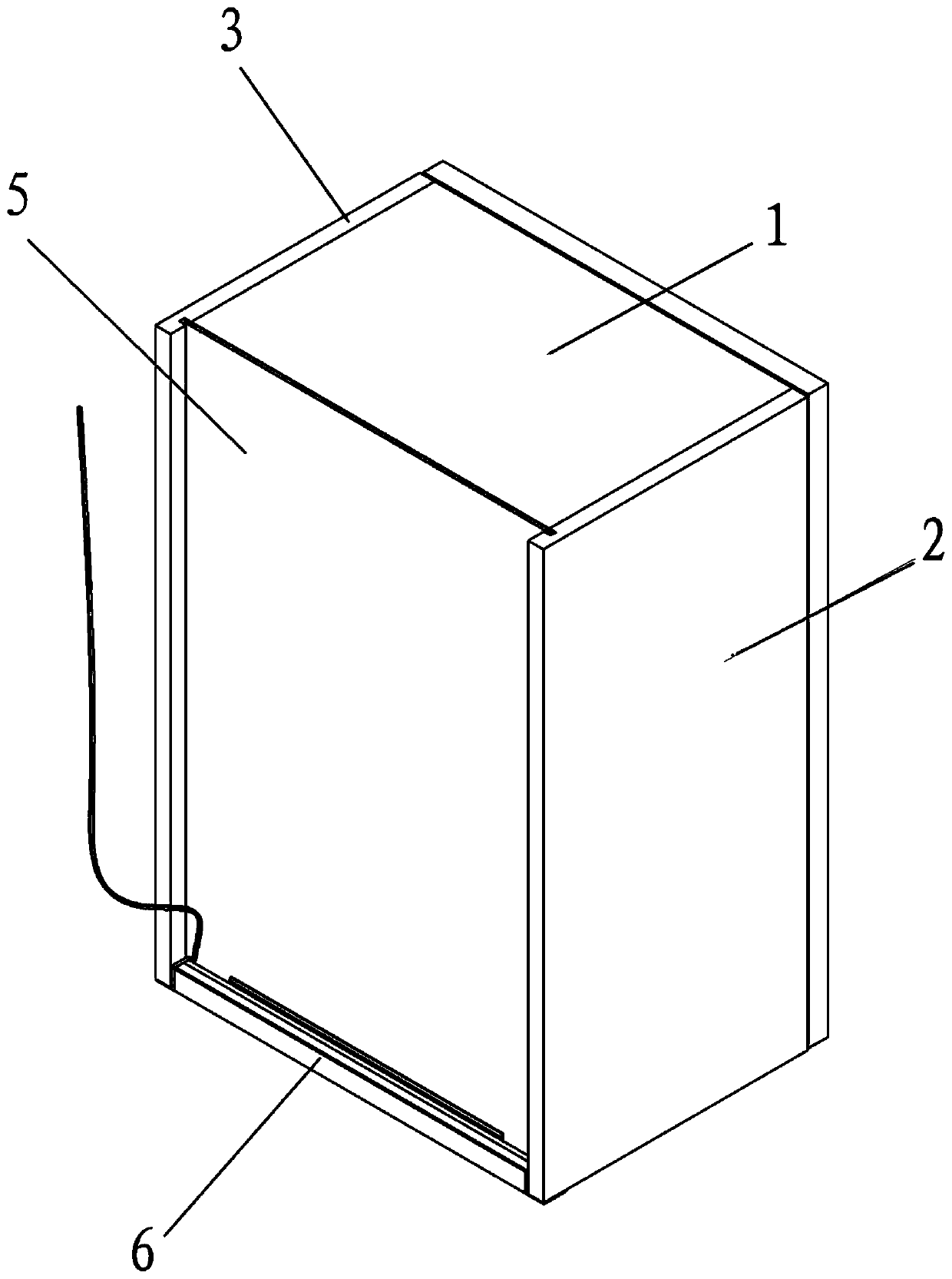
[0035] refer to Figure 1 to Figure 5 , the present embodiment provides a wall cabinet installed on the wall, including a top board 1, a left side board 2, a right side board 3, a bottom board (not shown in the figure) and a back board 5, wherein the left side board 2, The top plate 1, the right side plate 3, and the bottom plate are vertically fixedly connected in sequence to form a frame structure. The sides of the back plate 5 are respectively connected with the top plate 1, the left side plate 2, the right side plate 3, and the bottom plate. The back plate 5 is close to the wall and There is a gap between it and the wall, and an LED caulking lamp structure 6 is provided in the gap, and an LED caulking lamp structure 6 is provided on the bottom of the back plate 5 and on the side close to the wall.
[0036] From figure 1 It can be seen that the LED caulking light structure 6 extends from the left side panel 2 to the right side panel 3 . In this embodiment, the LED caulkin...
Embodiment 2
[0051] On the basis of Embodiment 1, this embodiment provides a wall cabinet, which includes all the technical features of the wall cabinet in Embodiment 1. The wall cabinet in the present embodiment also includes a first door panel and a second door panel, the first door panel is connected with the left side panel 2 by a hinge, and the second door panel is connected with the right side panel 3 by a hinge. The installation of the first door panel and the second door panel makes the wall cabinet form a closed space, which looks more tidy.
[0052] Certainly, in some optional embodiments, both the first door panel and the second door panel include glass.
Embodiment 3
[0054] On the basis of Embodiment 1, this embodiment provides the installation process of the above wall cabinet:
[0055] 1. The left side board 2, the top board 1, the right side board 3, and the bottom board are connected vertically in sequence to form a frame structure;
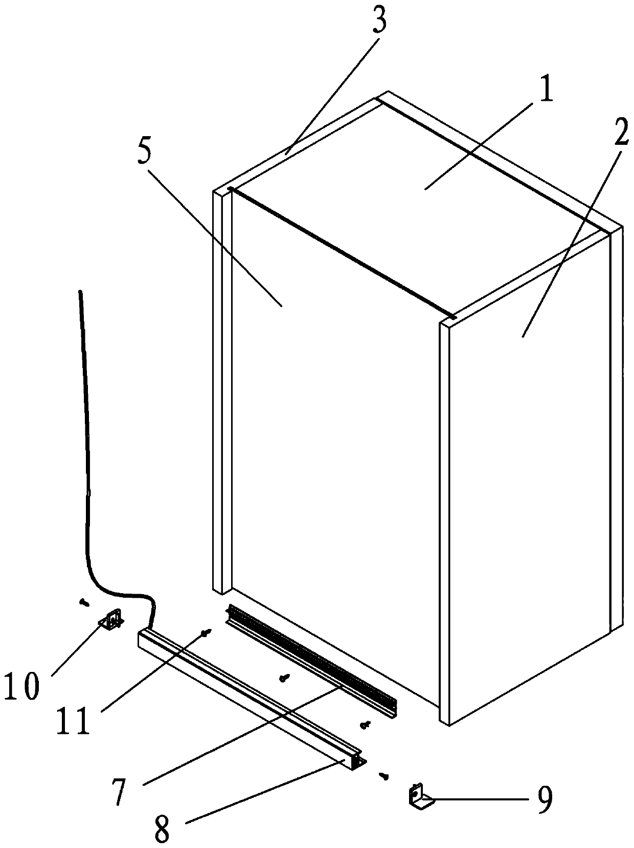
[0056] 2. Fix the first assembly 7 on the backplane 5 and the baseboard with self-tapping screws 11 at the bottom of the backplane 5. It can be seen from the figure that the self-tapping screws 11 penetrate the backplane 5 and then nail into the bottomboard;
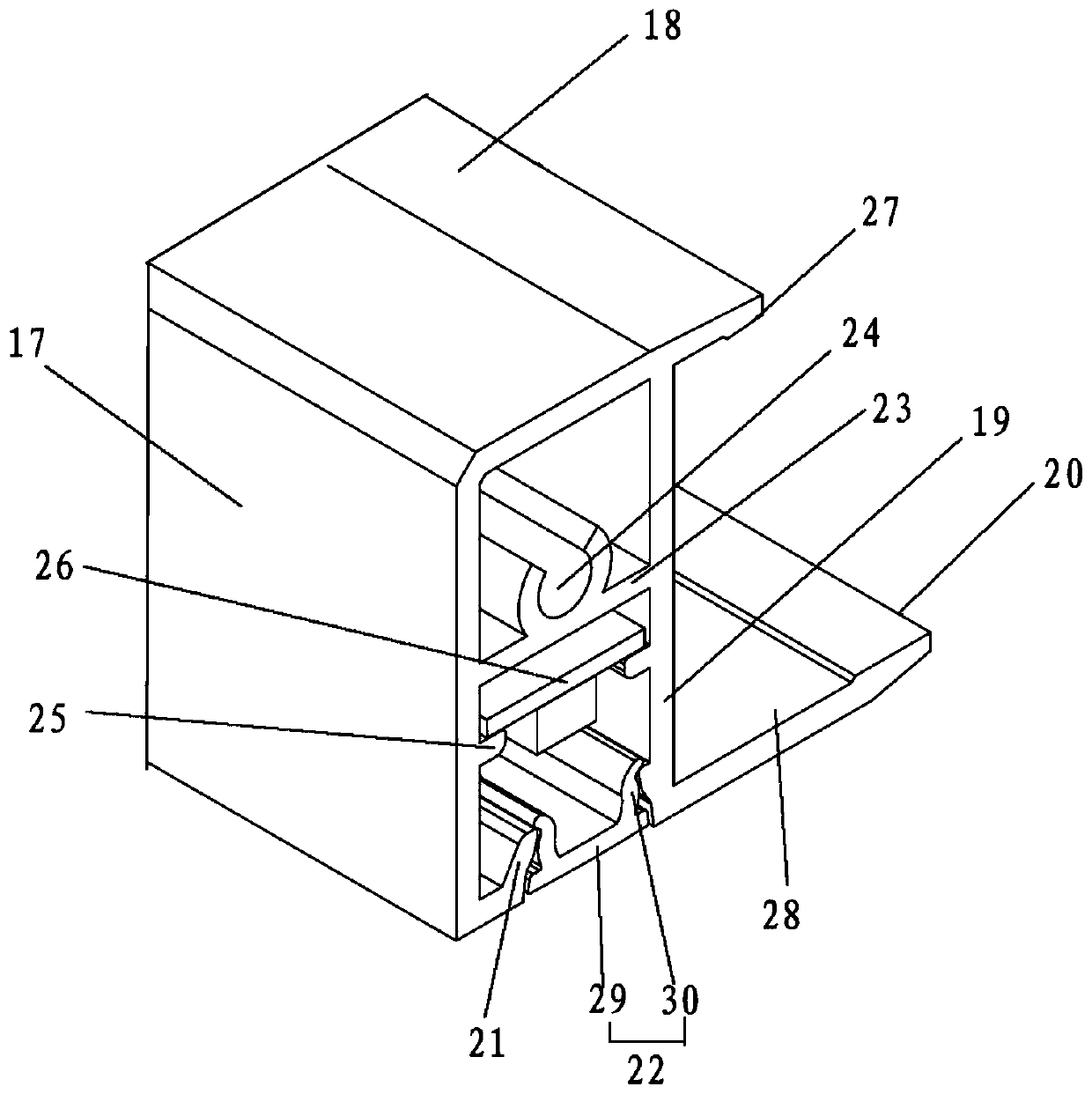
[0057] 3. Assemble the LED light strip 26 and the LED lampshade 22 into the second component 8, then fix the left decorative cover 9 and the right decorative cover 10 on the left and right sides of the second component 8 respectively, and then connect the second component 8 with the second component The two components 8 are engaged. Specifically, the third protrusion 27 on the fifth connecting plate 18 in the second component 8 is engaged with the f...
PUM
 Abstract
Description
Claims
Application Information