Concrete feeding vehicle walking device and concrete feeding vehicle

A traveling device and feeding car technology, applied in conveyors, mechanical conveyors, transportation and packaging, etc., can solve the problems of large wear, derailment, and loud noise of traveling wheels, and achieve the effect of increasing service life.

Pending Publication Date: 2019-10-08
CHANGSHA BROAD HOMES IND ANHUI CO LTD
View PDF1 Cites 0 Cited by
  • Summary
  • Abstract
  • Description
  • Claims
  • Application Information

AI Technical Summary

Problems solved by technology

When the concrete is conveyed from the mixing station to the corresponding station through the circular track through the concrete feeding vehicle, since the walking wheels of the concrete feeding vehicle do not have the steering function, the feeding hopper needs to slow down when passing the corner of the track, and it needs to rely on the walking wheels and The forced extrusion between the sides of the track makes the concrete feed truck achieve the purpose of turning, which causes great wear and tear on the traveling wheels, and there is a lot of noise
[0003] In addition, when the concrete feed truck passes the corner of the circular track at a relatively high speed, it is prone to derailment, causing potential safety hazards
[0004] Patent CN201620666949.X discloses a track-type conveyor. Guide wheels are arranged on both sides of the track, which can ensure that the moving direction of the track-type conveyor is always consistent with the track to a certain extent, but the guide wheels are always fixed relative to the connecting frame. Unable to cope with the scene where the track conveyor passes through a curve or a circular track

Method used


Image

  • Concrete feeding vehicle walking device and concrete feeding vehicle
  • Concrete feeding vehicle walking device and concrete feeding vehicle
  • Concrete feeding vehicle walking device and concrete feeding vehicle

Examples


Embodiment Construction

[0030] In order to facilitate the understanding of the present invention, the present invention will be described more fully below with reference to the associated drawings. Preferred embodiments of the invention are shown in the accompanying drawings. However, the present invention can be embodied in many different forms and is not limited to the embodiments described herein. On the contrary, these embodiments are provided to make the understanding of the disclosure of the present invention more thorough and comprehensive.

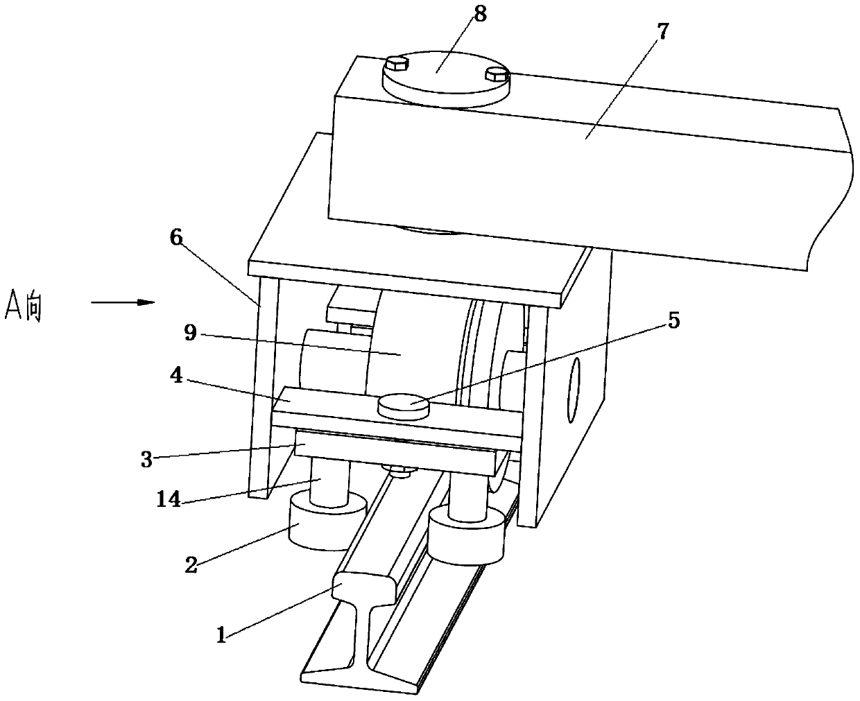
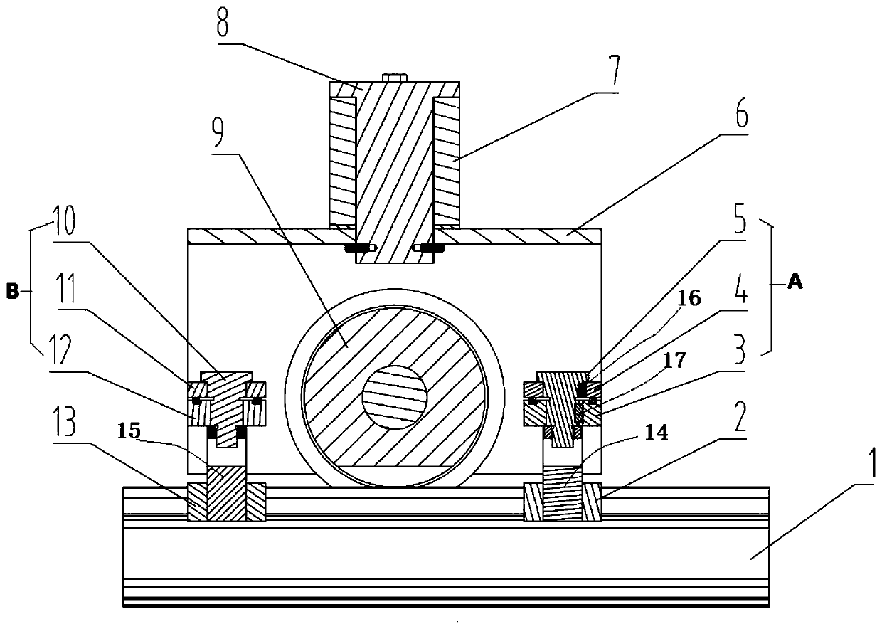
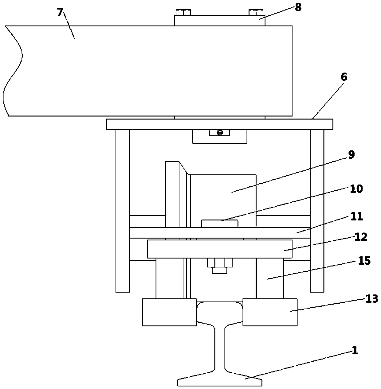
[0031] Such as Figure 1 to Figure 3 As shown, a concrete feeding vehicle walking device includes a mounting frame 6, a walking wheel 9 for the concrete feeding vehicle to walk on the track 1, a first guide wheel set and a second guide wheel set, the walking wheels 9, The first guide wheel group and the second guide wheel group are all installed on the mounting frame 6, and the traveling wheels 9 are located between the first guide wheel group and the s...


PUM


Abstract

The invention discloses a concrete feeding vehicle walking device and a concrete feeding vehicle. The walking device comprises a mounting frame, walking wheels, a first guide wheel set and a second guide wheel set; the walking wheels, the first guide wheel set and the second guide wheel set are all mounted on the mounting frame; the first guide wheel set comprises a first connecting mechanism, andtwo first guide wheels mounted on the first connecting mechanism; the second guide wheel set comprises a second connecting mechanism, and two second guide wheels mounted on the second connecting mechanism; the first connecting mechanism is fixedly connected with the mounting frame; the first guide wheels are rotationally mounted on the first connecting mechanism; the second connecting mechanism is rotationally fixed on the mounting frame; and the second guide wheels are rotationally mounted on the second connecting mechanism. The walking device can be freely steered along with the rail path change to prolong the service life of the walking wheels and rails, can guarantee no derailing in the operation process on the rails, and can pass through any position of rail paths at a higher speed.

Description

technical field [0001] The invention relates to the field of construction machinery, in particular to a walking device for a concrete feeding vehicle and a concrete feeding vehicle. Background technique [0002] At present, concrete feeding trucks are often used in construction sites or PC prefabricated parts production sites. When the concrete is transported from the mixing station to the corresponding station through the circular track through the concrete feeding vehicle, since the walking wheels of the concrete feeding vehicle do not have the steering function, the feeding hopper needs to slow down when passing the corner of the track, and it needs to rely on the walking wheels and The forced extrusion between the sides of the track makes the concrete feed truck achieve the purpose of turning, which causes great wear and tear on the traveling wheels and makes a lot of noise. [0003] In addition, when the concrete feeding truck passes the corner of the circular track at...

Claims


Application Information

Patent Timeline
IPC IPC(8): B65G35/00
CPCB65G35/00
Inventor 张剑陈小青
Owner CHANGSHA BROAD HOMES IND ANHUI CO LTD
Why Eureka
Try Eureka