
Portable type rope winding device

A winder, portable technology, applied in the field of power transmission line maintenance equipment, can solve the problems of small circle diameter, difficult to take out, inconvenient to use, etc., to achieve the effect of being conducive to management and uniform length of inner diameter

Pending Publication Date: 2019-10-08
QUJING POWER SUPPLY BUREAU YUNNAN POWER GRID CO LTD
View PDF0 Cites 0 Cited by
  • Summary
  • Abstract
  • Description
  • Claims
  • Application Information

AI Technical Summary

Problems solved by technology

The disc rope winder on the market is a metal disc type with a small diameter. The rope is coiled up by shaking the handle, and then disassembled to take out the wound rope. For a rope longer than 100m, the coiled volume is large and difficult to take out. , plus the overall weight is greater than 10kg, it is inconvenient to use during work

Method used


Image

  • Portable type rope winding device
  • Portable type rope winding device
  • Portable type rope winding device

Examples


Embodiment 1

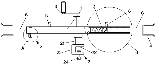
[0022] Figure 1-3 The portable rope winder shown includes a housing tube 1, which is rotatably arranged in the middle of the housing tube 1 and forms a T-shaped slot fixing mechanism 2 with the housing tube 1. The opposite hand handle 3 of the fixing mechanism 2 is symmetrically arranged at both ends of the housing tube 1, a U-shaped coil slot 4, and a clamping device for clamping the end of the rope is arranged at one end of the housing tube 1. Device 5; the U-shaped openings of the two wire slots 4 face away from each other to form a rope winding mechanism; the slot fixing mechanism 2 includes a connecting rod 21 that is rotatably connected to the middle of the casing tube 1 at one end, and is arranged on the cantilevered end of the connecting rod 21 There is a clamping seat 23 with a U-shaped opening 22 at the end and one side, and a handle bolt 24 screwed on the U-shaped opening 22 of the clamping seat 23; Structural connection; the telescopic and adjustable structure in...

Embodiment 2

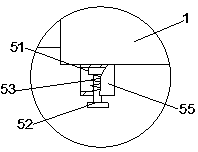
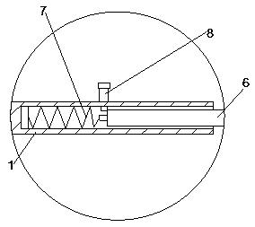
[0027] Figure 1-3 The portable rope winder shown in this example adopts a reset member and a clamping device different from that of Embodiment 1, and the rest are basically the same as Embodiment 1. Specifically, the reset part adopts a compression spring, and the compression spring is sleeved on the guide rod. The end of the guide rod is provided with a limit portion 9 at one end of the limit compression spring, and a limit portion 9 at the other end of the limit compression spring is set on the housing tube. Structure 10, the specific structure design is as follows Figure 6 As shown, the compression spring can keep the guide rod in a retracted state, while the spring pin can make the guide rod be positioned within its moving range, which can be positioned by slot positioning, non-positioning at the end or frictional resistance. The clamping device 5 includes a bracket 55 arranged at one end of the housing pipe 1, and a compression bolt 54 screwed on the bracket 55. The en...


PUM

PropertyMeasurementUnit
Diameteraaaaaaaaaa

Abstract

The invention discloses a portable type rope winding device. The device is small in size and convenient to use. The device comprises a shell tube, a clamping groove fixing mechanism which is rotatablyarranged in the middle of the shell tube and forms a T shape with the shell tube, a hand crank fixedly arranged in the middle of the shell tube and opposite to the clamping groove fixing mechanism, two wire coiling grooves which are symmetrically formed in the two ends of the shell tube and are in U shapes, and a clamping device arranged at one end of the shell tube and used for clamping the endof a rope, U openings of the two wire coiling grooves are away from each other, the clamping groove fixing mechanism comprises a connecting rod with one end rotatably connected with the middle of theshell tube, a clamping base arranged at the overhanging end of the connecting rod and with one side provided with a U opening, and a handle bolt in screw connection to the U opening of the clamping base. The wire coiling grooves and the shell tube are connected through a telescopic adjusting structure, and the telescopic adjusting structure comprises a guide rod, a reset part arranged on the shelltube, and a spring plug pin arranged on the shell tube and used for locking the guide rod.

Description

technical field [0001] The invention relates to the technical field of maintenance equipment for power transmission lines, in particular to a portable rope winder. Background technique [0002] Rope is an indispensable tool in power transmission operation and maintenance. Rope materials and diameters vary. There are many types of ropes. In the daily maintenance of the power industry, fiber ropes and chemical fiber ropes are mainly used. It is silk rope, aramid fiber rope, high-strength polyethylene fiber rope, etc. The rope with a diameter of less than 10mm and a length of more than 100m is quite troublesome in the process of reeling and unwinding. The labor intensity of the operators also increases the working time. The disc rope winder on the market is a metal disc type with a small circumference diameter. The rope is coiled up by shaking the handle, and then disassembled to take out the wound rope. For a rope longer than 100m, the coiled volume is large and difficult to ...

Claims


Application Information

Patent Timeline
IPC IPC(8): B65H75/44B65H75/40B65H75/24
CPCB65H75/4492B65H75/40B65H75/242B65H2701/35
Inventor 张宇雄吴恒张海东周晴邓中原时峰陈宣林张方磊宋凯易黎刘秀梅
Owner QUJING POWER SUPPLY BUREAU YUNNAN POWER GRID CO LTD
Learn More