
A shaft end power generation structure of a railway vehicle

A railway vehicle and shaft end technology, which is applied in the field of shaft end power generation structures, can solve problems such as the inapplicability of shaft end power generation schemes, and achieve the effects of low cost, improved protection performance, and safe design

Active Publication Date: 2020-06-12
CSR ZHUZHOU ELECTRIC LOCOMOTIVE RES INST
View PDF7 Cites 0 Cited by
  • Summary
  • Abstract
  • Description
  • Claims
  • Application Information

AI Technical Summary

Problems solved by technology

However, since most of the bogies of existing railway vehicles are three-piece bogies with no axle box structure, the shaft end power generation schemes of patents above three-piece bogies are not applicable

Method used


Image

  • A shaft end power generation structure of a railway vehicle
  • A shaft end power generation structure of a railway vehicle
  • A shaft end power generation structure of a railway vehicle

Examples


Embodiment Construction

[0028] In order to make the object, technical solution and advantages of the present invention clearer, the present invention will be described in further detail below in conjunction with specific embodiments and with reference to the accompanying drawings.

[0029] It should be noted that all expressions using "first" and "second" in the embodiments of the present invention are used to distinguish two entities with the same name but different parameters or parameters that are not the same, see "first" and "second" It is only for the convenience of expression, and should not be construed as a limitation on the embodiments of the present invention, which will not be described one by one in the subsequent embodiments.

[0030] An embodiment of the present invention provides an axle end power generation structure of a railway vehicle, aiming to solve the technical problem that the axle end power generation scheme in the prior art cannot be applied to a railway vehicle using a thre...


PUM


Abstract

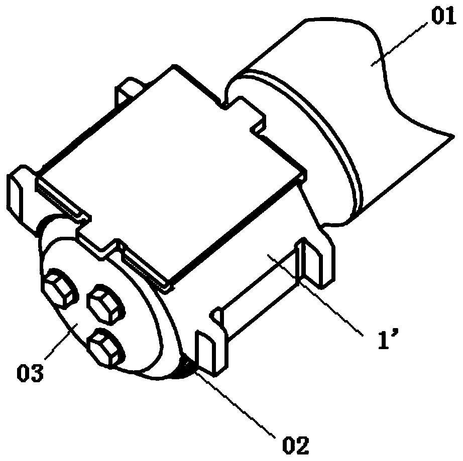
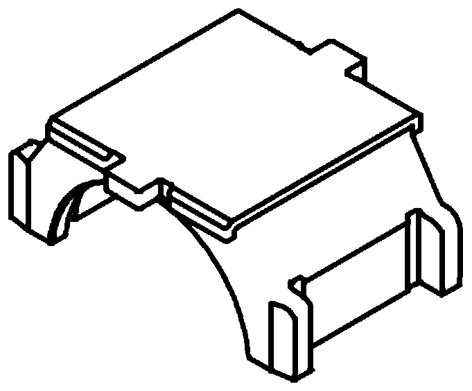
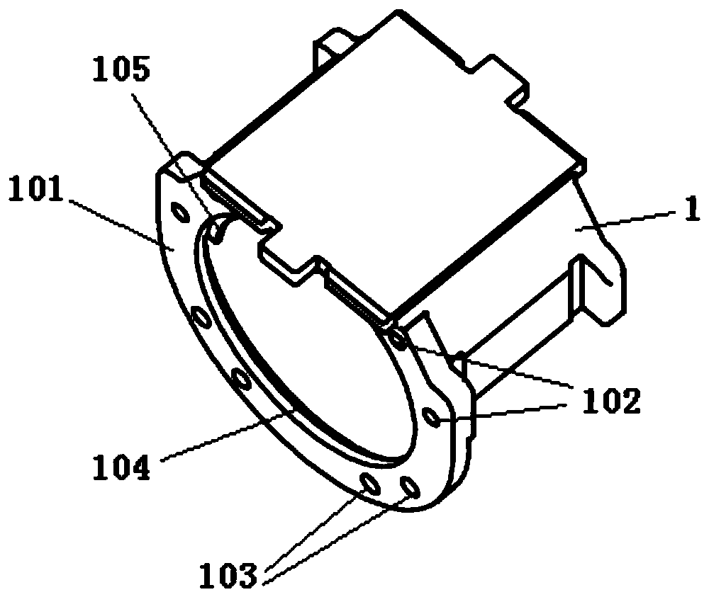
The invention discloses a axle end power generation structure of a railway vehicle, which comprises a bearing saddle, a guard ring and a generator, wherein the bearing saddle has a cylindrical surfacestructure, the side surface of the bearing saddle comprises an annular mounting surface, and the mounting surface is used for mounting the generator; the guard ring is disposed at a gap between the bearing saddle and the axle bearing, and the inner circle of the guard ring is matched with the outer circle clearance of the axle bearing; and the generator comprises a stator and a rotor, the statoris fixed on the mounting surface, and the rotor is fixed on the axle end. The axle end power generation structure which can be applied to the railway vehicle by using a three-piece bogie has the advantages of being high in reliability, high in protection, small in size, light in weight, maintenance-free and small in bogie change.

Description

technical field [0001] The invention relates to the technical field of railway vehicles, in particular to an axle end power generation structure of a railway vehicle. Background technique [0002] With the increase of operating speed and load of railway vehicles, more and more electrical devices are widely used in railway vehicle systems, but limited by the structural characteristics and working environment of railway vehicles, traditional power supply methods are difficult to implement . Common power generation schemes for railway vehicles in the prior art include various power generation methods such as installing storage battery devices, shaft-end pulley drive generator generators, solar power generators, wind power generators, and bearing generators. Due to the limitation of technical level, the above power generation methods have relatively large shortcomings in terms of reliability, power generation, service life, and harsh working environment. Compared with the abov...

Claims


Application Information

Patent Timeline
Patent Type & Authority Patents(China)
IPC IPC(8): H02K7/18H02K1/12H02K1/18H02K1/27H02K5/10H02K5/24
CPCH02K1/12H02K1/18H02K1/2706H02K5/10H02K5/24H02K7/1846
Inventor 冯守智罗英露李伟业邹煜林王禹刘春秀李坤刘雄盛振强何思源
Owner CSR ZHUZHOU ELECTRIC LOCOMOTIVE RES INST
Learn More