
Differential resonator and MEMS sensor

A resonator and differential technology, applied in the field of MEMS sensors, can solve the problems of small quality factor, weak correction effect, and low robustness of differential resonator process, so as to suppress process error, excellent consistency, and improve process robustness Effect

Pending Publication Date: 2019-10-08
AAC TECH NANJING
View PDF4 Cites 1 Cited by
  • Summary
  • Abstract
  • Description
  • Claims
  • Application Information

AI Technical Summary

Problems solved by technology

[0004] However, in the manufacturing process of the differential resonator 4, the geometric dimensions of the first resonator 41 and the second resonator 42 cannot be almost identical
[0005] like image 3 As shown, under the driving action of the same external force, the first resonator 41 and the second resonator 42 will produce different amplitude outputs, that is, the displacement X of the first resonator 41 and the second resonator 42 in the same vibration direction A ≠X B , will force the coupling mechanism 43 to move △X in the unconstrained X direction. Therefore, the rectangular coupling mechanism has an effect on X A 、X B The correction effect of the difference is weak, so the traditional differential resonator has the disadvantages of low process robustness, small quality factor, and poor common-mode interference suppression ability

Method used


Image

  • Differential resonator and MEMS sensor
  • Differential resonator and MEMS sensor
  • Differential resonator and MEMS sensor

Examples


Embodiment Construction

[0030] In order to make the object, technical solution and advantages of the present invention clearer, the present invention will be further described in detail below in conjunction with the accompanying drawings and embodiments. It should be understood that the specific embodiments described here are only used to explain the present invention, not to limit the present invention.

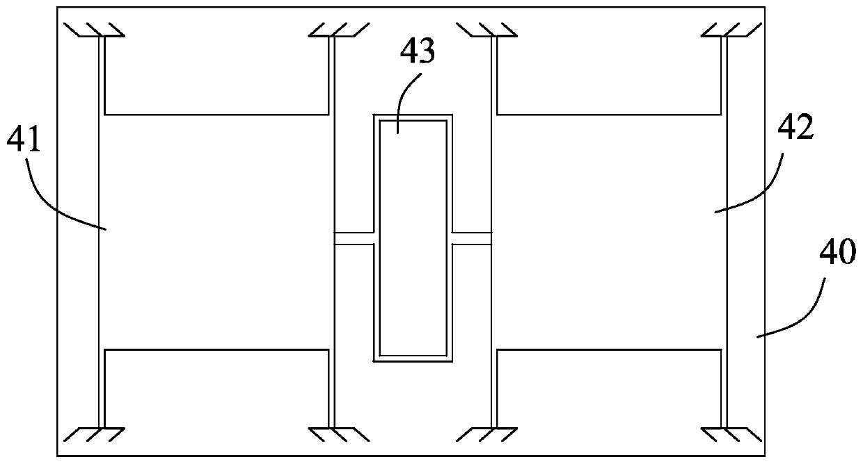
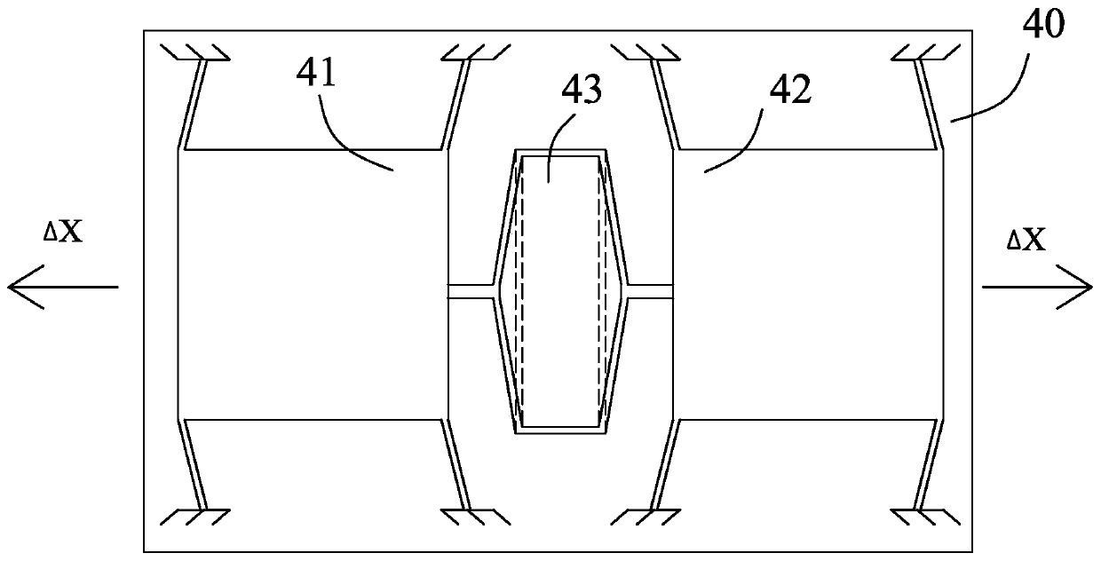
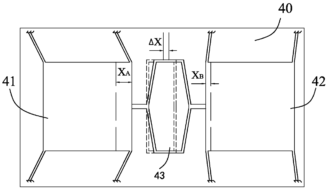
[0031] see Figure 4-6 , the present invention provides a differential resonator 1, the differential resonator 1 includes a substrate 10, a first resonator 11, a second resonator 12 and a coupling mechanism 13, the first resonator 11 is connected to the second resonator 12 through the coupling mechanism 13 connected, and the first resonator 11 and the second resonator 12 are connected to the base 10 and can be displaced relative to the base 10 under the action of an external force.

[0032] Specifically, the first resonator 11 includes a first vibrator 111 and a plurality of first connecting arms ...


PUM


Abstract

The invention provides a differential resonator and an MEMS sensor. The differential resonator comprises a substrate, a first resonator, a second resonator and a coupling mechanism. The first resonator is connected with the second resonator through the coupling mechanism, the first resonator and the second resonator are connected with the substrate and can move relative to the substrate under theaction of external force, and the coupling mechanism comprises a first guide beam, a second guide beam, a first coupling beam, a second coupling beam, a first connecting piece and a second connectingpiece. The first guide beam and the second guide beam are arranged on the two opposite sides of the direction perpendicular to the vibration direction of the first resonator or the second resonator. One end of the first coupling beam is connected with the first guide beam, the other end of the first coupling beam is connected with the second guide beam, and the first coupling beam is connected with the first resonator through the first connector. One end of the second coupling beam is connected with the first guide beam, the other end of the second coupling beam is connected with the second guide beam, and the second coupling beam is connected with the second resonator through the second connector.

Description

【Technical field】 [0001] The invention relates to the technical field of MEMS (Micro Electromechanical Systems, micro mechanical electronic systems) sensors, in particular to a differential resonator and a MEMS sensor. 【Background technique】 [0002] The differential resonator has a higher quality factor, which can suppress common-mode interference such as external acceleration, vibration, and temperature, and can effectively reduce the circuit noise level. Therefore, the use of differential motion modes is an optimized mainstream solution to improve the performance of MEMS sensors. [0003] Such as Figure 1-2 As shown, the traditional differential resonator 4 includes a first resonator 41, a second resonator 42, a coupling mechanism 43 connecting the first resonator 41 and the second resonator 42, and a substrate 40, wherein the first resonator 41 , the second resonator 42 and the coupling mechanism 43 connecting the first resonator 41 and the second resonator 42 are all ...

Claims


Application Information

Patent Timeline
IPC IPC(8): H03H9/02
CPCH03H9/02433H03H2009/0248G01C19/574H03H9/2405H03H9/09H03H2009/02291
Inventor 占瞻李杨刘雨薇陈秋玉张睿
Owner AAC TECH NANJING
Learn More