Feeding device of heating furnace
A feeding device and heating furnace technology, which is applied to lighting and heating equipment, furnaces, furnace components, etc., can solve the problems of high labor intensity of workers, long time for billets to be released from the furnace, and reduce manual operation time and labor intensity. The effect of speeding up the feeding speed and improving production efficiency
Inactive Publication Date: 2019-10-11
湖北长怡特殊材料科技有限公司
View PDF0 Cites 0 Cited by
- Summary
- Abstract
- Description
- Claims
- Application Information
AI Technical Summary
Problems solved by technology
When the heated billet comes out of the furnace, it is also clamped by the worker with a jig. The disadvantages of the existing method are: long time and low efficiency: only one billet can be clamped at a time. After clamping, it is necessary to push the billet into the furnace with a bar location, waste of time, and low efficiency; the billet takes a long time to come out of the furnace, and the safety of the workers is low: the heated billet can only be clamped by the worker with a clamp, and the temperature is higher than 1000 ° C, which is prone to danger; the labor intensity of the workers is high
Method used
View moreImage
Smart ImageViewing Examples

Examples
Embodiment Construction
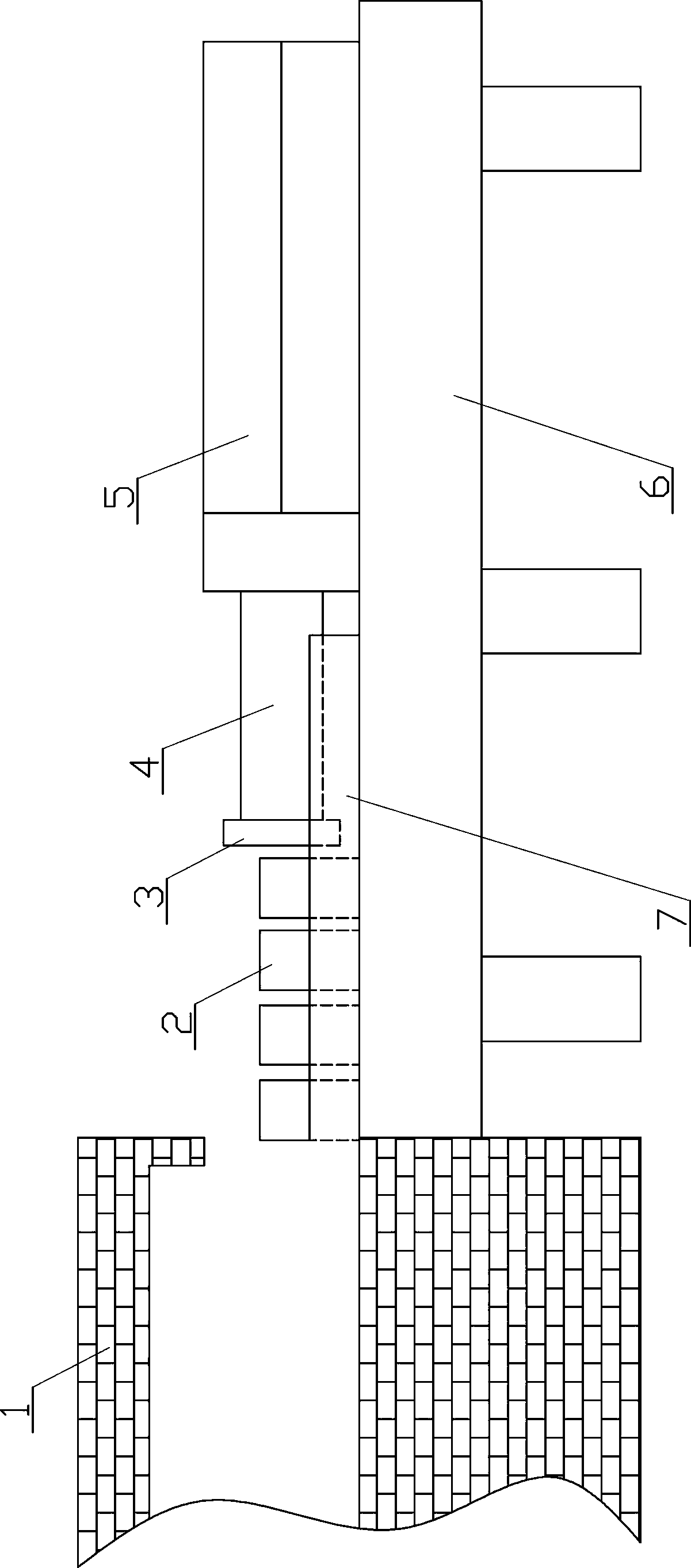
[0009] see figure 1 , the present embodiment includes a base 6 fixed on one side of the feed port of the heating furnace 1, the upper front end of the base 6 is used to place the material 2 to be heated, the upper rear end of the base 6 is fixedly equipped with an oil cylinder 5, and the front end of the piston rod 4 of the oil cylinder 5 A push plate 3 is housed.
[0010] The front end of the upper surface of the base 6 in this embodiment is equipped with a material slideway 7 .
Login to View More PUM
 Abstract
The invention relates to the field of heating furnace auxiliary equipment, in particular to a feeding device of a heating furnace. The feeding device comprises a base fixed to one side of a feeding hole of the heating furnace; the upper front end of the base is used for holding a material to be heated; the upper rear end of the base is fixedly provided with an oil cylinder; and a piston rod of theoil cylinder is provided with a push plate. The feeding device of the heating furnace greatly shortens the manual operating time and reduces the labor strength, and greatly lowers the potential safety hazard.
Description
technical field [0001] The invention relates to the field of heating furnace auxiliary equipment, in particular to a heating furnace feeding device. Background technique [0002] The existing billet heating is to manually clamp the billet into the furnace, and only one billet can be clamped at a time, and then the billet is pushed to the designated position with a special bar for pushing the billet. When the heated blank comes out of the furnace, it is also clamped by the worker with a clamp. The disadvantages of the existing method are: long time and low efficiency: only one blank can be clamped at a time. After clamping, it is necessary to use a bar to push the blank into the furnace to specify The location wastes time and the efficiency is very low; the billet takes a long time to come out of the furnace, and the safety of the workers is low: the heated billet can only be clamped by the worker with a clamp, and the temperature is higher than 1000 ° C, which is prone to da...
Claims
Login to View More Application Information
Patent Timeline
 IPC IPC(8): F27D3/00
CPCF27D3/0084F27D2003/0001
Inventor 陈俊波刘鹏涛卢敏
Owner 湖北长怡特殊材料科技有限公司