Method and apparatus for winding band-shaped rubber member

A winding device and rubber technology, which is applied to tires, household appliances, and other household appliances, can solve the problems of different cross-sectional shapes and deformation, and achieve the effect of suppressing the amount of deformation

Inactive Publication Date: 2019-10-11
BRIDGESTONE CORP
View PDF9 Cites 0 Cited by
  • Summary
  • Abstract
  • Description
  • Claims
  • Application Information

AI Technical Summary

Problems solved by technology

[0005] In this way, in the past, it was intended to form a tread with a target cross-sectional shape by overlapping and winding a belt-shaped rubber member on the outer periphery of the tire intermediate body, but there was a problem that the cross-sectional shape of the belt-shaped rubber member was often not supplied to the tire intermedi

Method used


Image

  • Method and apparatus for winding band-shaped rubber member
  • Method and apparatus for winding band-shaped rubber member
  • Method and apparatus for winding band-shaped rubber member

Examples


Embodiment approach 1

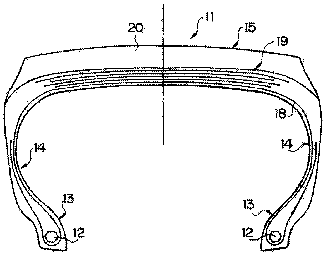
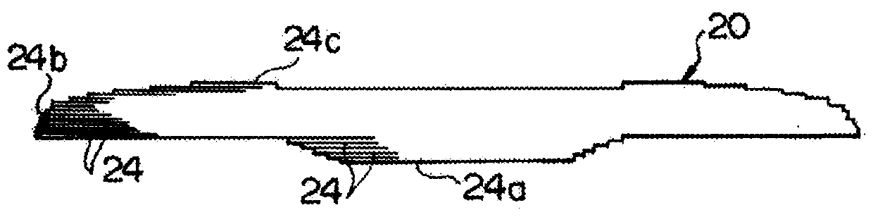
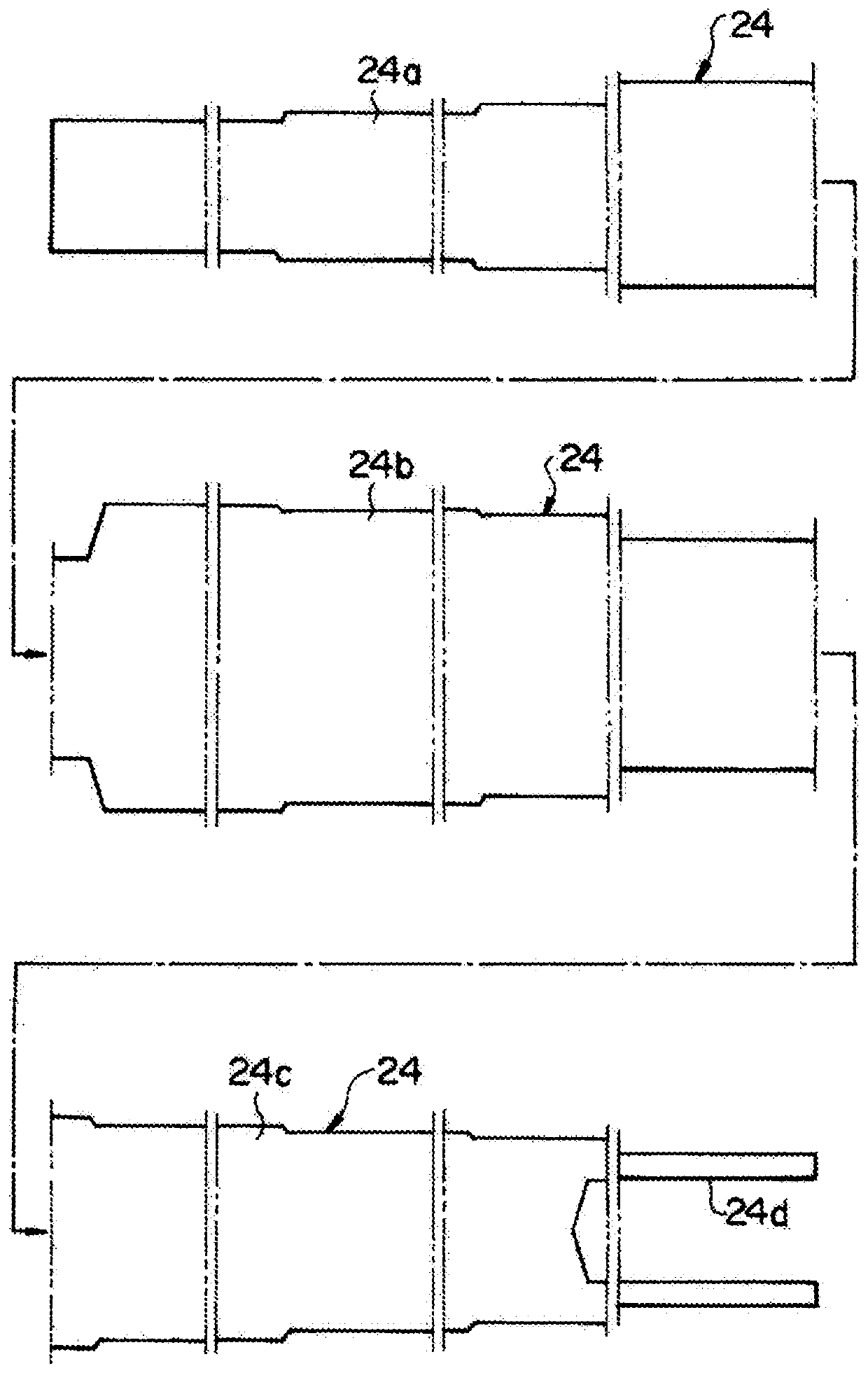
[0018] exist figure 1 Among them, reference numeral 11 is a vulcanized pneumatic radial tire mounted on a large construction vehicle. This tire 11 has a pair of bead portions 13 in which annular beads 12 are respectively embedded, a pair of sidewall portions 14 extending generally radially outward from the bead portions 13 , and the sidewall portions 14 described above. A substantially cylindrical tread portion 15 in which radially outer ends are connected to each other. Further, the tire 11 is reinforced with a ring-shaped carcass layer 18 extending from one bead portion 13 to the other bead portion 13 . Both ends in the width direction of the carcass layer 18 are folded back around the beads 12 . A belt layer 19 is disposed radially outside the carcass layer 18 . Further, a tread 20 is arranged radially outside the belt layer 19 , and grooves having a wide width are formed on the outer surface (contact surface) of the tread 20 . Here, the aforementioned tread 20 is form...


PUM


Abstract

An apparatus for winding a band-shaped rubber member comprises: a measurement unit which measures at a measurement point P a measured width and a measured thickness of a band-shaped rubber member immediately before being wound; and a difference acquisition unit which obtains, while taking into consideration a deformation of the band-shaped rubber member, a predicted width and a predicted thicknessof the band-shaped rubber member at the measurement point P from a target width and a target thickness of the band-shaped rubber member derived from a target cross-sectional shape of a tread, and which determines differences between the measured width and measured thickness and the predicted width and predicted thickness at each corresponding position in a longitudinal direction.

Description

technical field [0001] The present disclosure relates to a method and an apparatus for winding a belt-shaped rubber member for forming a tread by overlapping and winding a belt-shaped rubber member a plurality of times around the outer periphery of an annular tire intermediate body. Background technique [0002] As a conventional method of winding a belt-shaped rubber member, for example, the technique described in JP 2011-183623 A is known. [0003] This technology includes a rotating unit for rotating a ring-shaped tire intermediate around an axis, and supplying a belt-shaped rubber member to the outer periphery of the tire intermediate and winding it a plurality of times to form a tread having a target cross-sectional shape. The belt-shaped rubber member between the supply part and the tire intermediate travels in the air by disposing the supply part away from the tire intermediate. Contents of the invention [0004] The problem to be solved by the invention [0005]...

Claims


Application Information

Patent Timeline
IPC IPC(8): B29D30/60
CPCB29D30/60B29D30/1628B29D2030/0066B29D30/1621
Inventor 一户徹
Owner BRIDGESTONE CORP
Why Eureka
Try Eureka