Vehicle lower section structure

a lower section and battery technology, applied in the field of vehicle lower section structure, can solve problems such as battery deformation, and achieve the effect of suppressing battery deformation

Active Publication Date: 2018-05-10
TOYOTA JIDOSHA KK
View PDF33 Cites 22 Cited by
  • Summary
  • Abstract
  • Description
  • Claims
  • Application Information

AI Technical Summary

Benefits of technology

[0005]In consideration of the above circumstances, the present disclosure provides a vehicle lower section structure capable of suppressing deformation of a battery.
[0009]Moreover, during a vehicle rear-end collision, collision load that has been input to the second cross-member is transmitted to the first cross-member through at least one of the pair of rear side-members. Deformation of the first cross-member, the second cross-member, and the pair of rear side-members is accordingly suppressed during a vehicle collision due to collision load being distributed and transmitted to the first cross-member, the second cross-member, and the pair of rear side-members in this manner. The first cross-member, the second cross-member, and the pair of rear side-members are therefore not as liable to contact the battery compared to a configuration in which the battery is not housed in the housing section, thereby enabling deformation of the battery to be suppressed.
[0015]In the vehicle lower section structure configured as described above, the seat frame is not only employed as a member to install the seat on, but also employed as a reinforcement member. The number of components is accordingly reduced, enabling a reduction in weight of the vehicle to be achieved.
[0017]In the vehicle lower section structure configured as described above, in order to dispose part of the rear side-members offset with respect to the bottom portion of the floor panel, the second cross-member is arranged on the inclined portion of the floor panel such that the height of the rear side-members and the height of the second cross-member are substantially aligned with each other. The second cross-member accordingly does not need to have a profile in which end portions at each vehicle width direction end thereof are offset in the vehicle vertical direction relative to a central portion thereof. Namely, the second cross-member may be disposed in a straight line along the vehicle width direction, enabling the size of the second cross-member to be smaller than in a configuration in which the second cross-member is offset, enabling a reduction in weight of the vehicle to be achieved.

Problems solved by technology

In such a vehicle lower section structure, in cases in which deformation of the vehicle body has occurred during a collision, there is a possibility of contact between the deformed vehicle body and the battery at the location where no framework member is provided, and a possibility of the battery being deformed.

Method used


Image

  • Vehicle lower section structure
  • Vehicle lower section structure
  • Vehicle lower section structure

Examples


first exemplary embodiment

[0031]Explanation follows regarding a vehicle lower section structure according to a first exemplary embodiment. In the drawings arrows FR indicate forward (the direction of progress) for a vehicle, arrows RR indicate rearward for the vehicle, arrows UP indicate upward, and arrows W indicate a vehicle width direction. Moreover, in the following, unless particularly stated otherwise, when explanation is given referring simply to front / rear, left / right, or up / down directions, these indicate front / rear in the vehicle front-rear direction, left / right in the vehicle width direction when facing in the direction of progress, and up / down in the vehicle vertical direction.

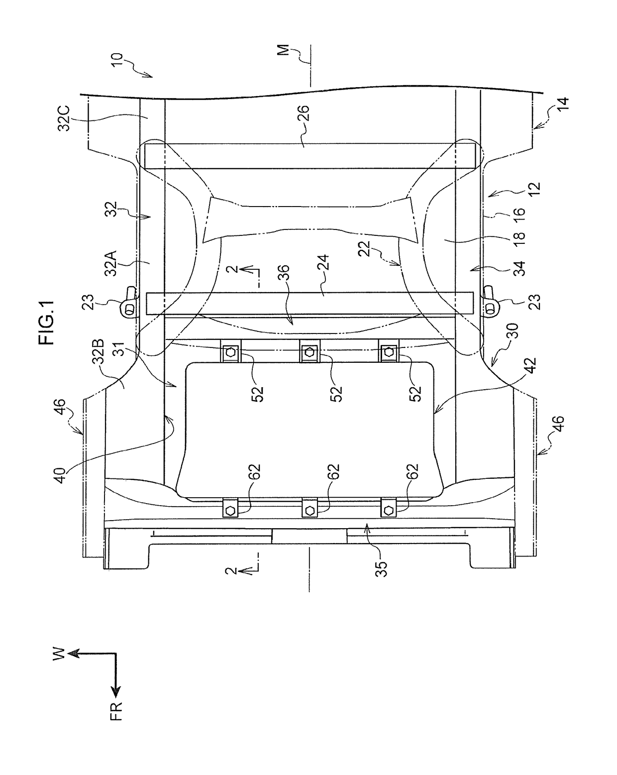
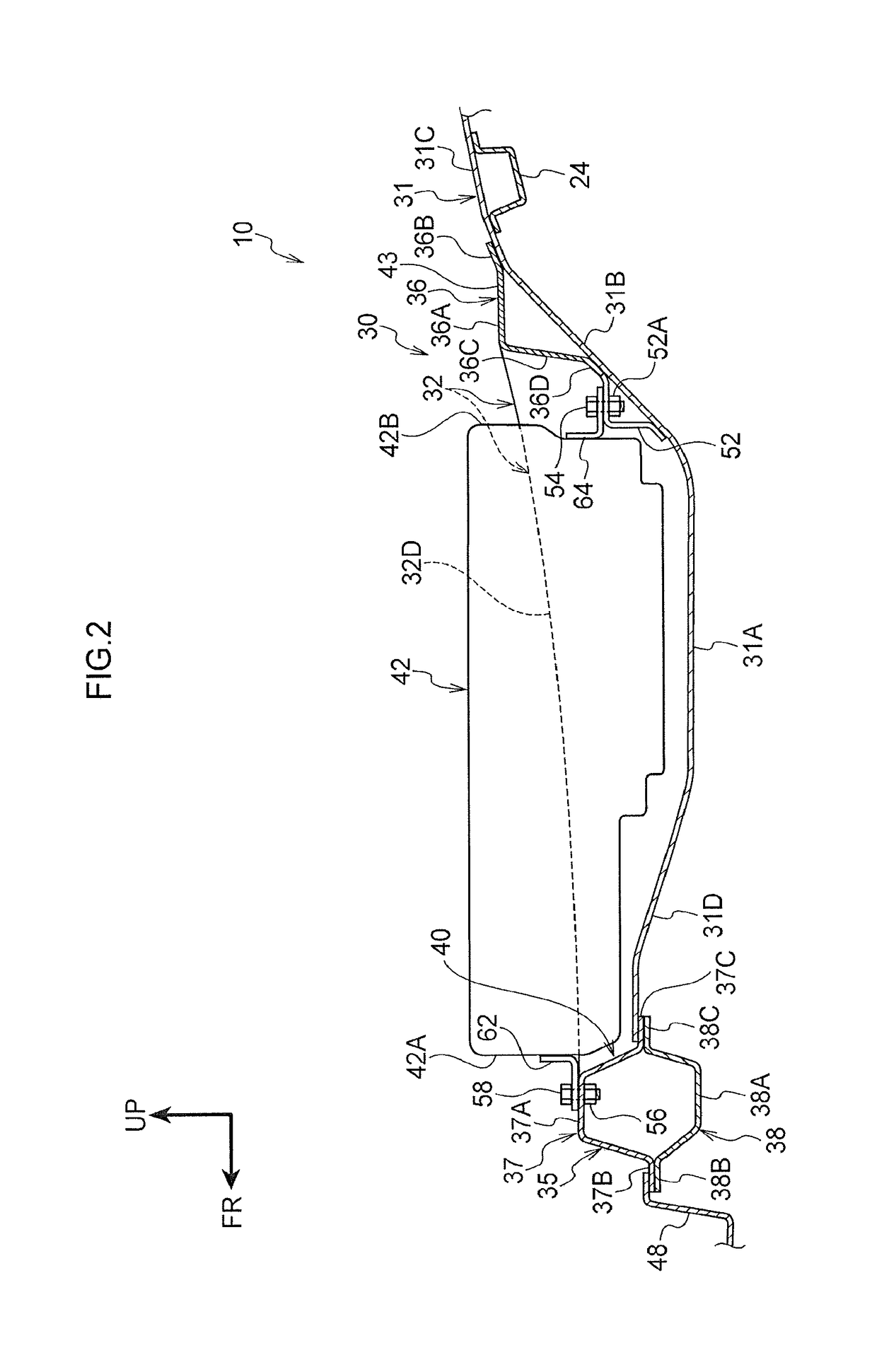
[0032]FIG. 1 illustrates part of a vehicle lower section 12 of a vehicle 10 of the first exemplary embodiment, from a central portion to a rear portion of the vehicle lower section 12 in the vehicle front-rear direction. The vehicle 10 is applied with a vehicle lower section structure 30, described later, and, for example, ...

second exemplary embodiment

[0075]Next, explanation follows regarding a vehicle lower section structure according to a second exemplary embodiment. Components and portions having similar function to those of the vehicle lower section structure 30 according to the first exemplary embodiment described above are appended with the same reference signs to those employed in the first exemplary embodiment, and explanation thereof is omitted.

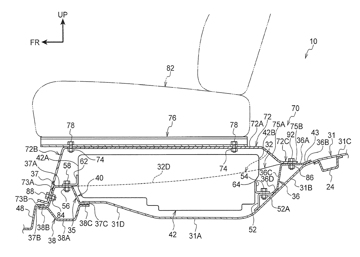
[0076]FIG. 7 and FIG. 8 illustrate a vehicle lower section structure 70 applied to a vehicle 10, as an example of the second exemplary embodiment. The vehicle lower section structure 70 includes rear side-members 32, 34, a first cross-member 35, a second cross-member 36, a battery 42, and seat frames 72. The vehicle lower section structure 70 includes rear suspension members 22, rear shock absorbers 23, and a suspension cross-member 24. As illustrated in FIG. 9, weld nuts 84 are provided on an inclined portion of the first cross-member 35 at a vehicle front side of a main body 37A...

modified examples

[0092]The present disclosure is not limited to the exemplary embodiments described above.

[0093]In the vehicle lower section structure 30, 70, instead of the inclined portion 31B, the bottom portion 31A may be extended toward the rear of the vehicle, and the second cross-member 36 may be arranged on the bottom portion 31A.

[0094]The reinforcement member is not limited to the seat frame 72 and may be configured by a different member to the seat frame 72. For example, a battery member disposed along the vehicle front-rear direction to reinforce the housing section 40 may be employed as a different body to the seat frame 72. Both the seat frame 72 and a battery member may be employed.

[0095]The seat frame 72 may be shaped such that, when viewed along the vehicle width direction, the main body 72A is positioned at substantially the same height as the first coupling portion 72B and the second coupling portion 72C, or such that the main body 72A is positioned in the vehicle vertical directio...


PUM


Abstract

A vehicle lower section structure includes: a pair of rear side-members that is disposed in a vehicle lower section so as to be separated from each other in a vehicle width direction, and that are extending in a vehicle front-rear direction; a first cross-member extending in the vehicle width direction, to which the rear side-members joined; a second cross-member extending in the vehicle width direction at the rear of the first cross-member in the vehicle front-rear direction, to which the rear side-members joined; and a battery that is housed in a housing section surrounded by the rear side-members, the first cross-member, and the second cross-member, at least part of the battery overlapping with the rear side-members when viewed along the vehicle width direction, and at least part of the battery overlapping with the first cross-member and the second cross-member when viewed along the vehicle front-rear direction.

Description

CROSS-REFERENCE TO RELATED APPLICATION[0001]This application is based on and claims priority under 35 USC 119 from Japanese Patent Application No. 2016-217458 filed on Nov. 7, 2016, the disclosure of which is incorporated by reference herein.BACKGROUNDTechnical Field[0002]The present disclosure relates to a vehicle lower section structure.Related Art[0003]A structure of a battery mounted vehicle is described in Japanese Patent Application Laid-Open (JP-A) No. 2011-126439. In the battery mounted vehicle, a battery is disposed in a vehicle vertical direction above a center cross-member, and at the front of a rear cross-member in a vehicle front-rear direction. A seat frame for a rear seat is fixed to an upper portion of the battery using a bracket.[0004]There are vehicle lower section structures that have no framework member for the vehicle body provided at part of the periphery of a battery installed in the vehicle body. In such a vehicle lower section structure, in cases in which de...

Claims


Application Information

Patent Timeline
Patent Type & Authority Applications(United States)
IPC IPC(8): B60K1/04B62D21/02B60N2/005B62D25/20B60G13/00
CPCB60K1/04B62D21/02B60N2/005B62D25/20B60G13/001B60K2001/0433B60N2/012B60Y2306/01
Inventor SAEKI, KOJI
Owner TOYOTA JIDOSHA KK
Why Eureka
Try Eureka