
Wire harness

A wire harness and wire technology, which is applied in the field of wire installation exterior components, can solve problems such as complex shapes and achieve the effect of simple installation

Active Publication Date: 2019-10-11
AUTONETWORKS TECH LTD +2
View PDF6 Cites 2 Cited by
  • Summary
  • Abstract
  • Description
  • Claims
  • Application Information

AI Technical Summary

Problems solved by technology

In addition, if a single exterior part of a molded product corresponds to a flat area and a curved area, problems such as complicated shape will arise.

Method used


Image

  • Wire harness
  • Wire harness
  • Wire harness

Examples


Embodiment Construction

[0032] {implementation method}

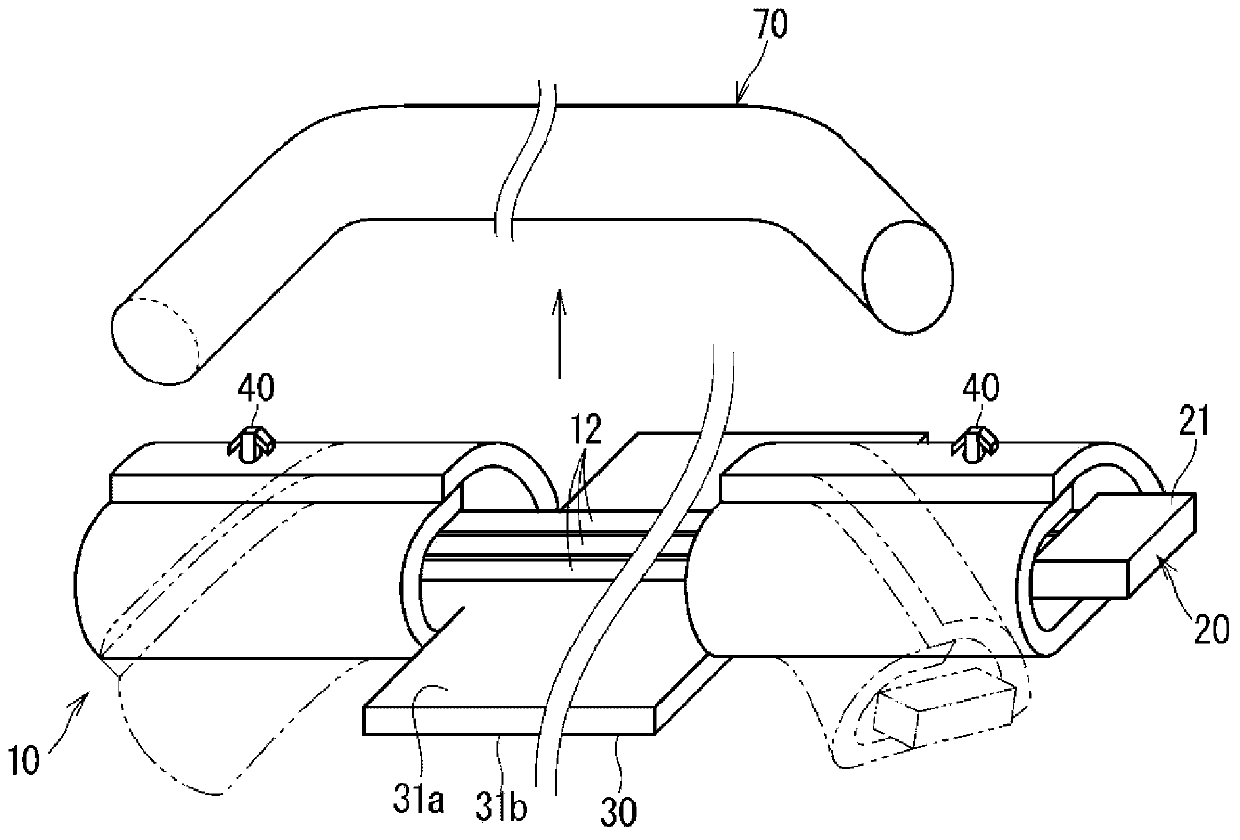
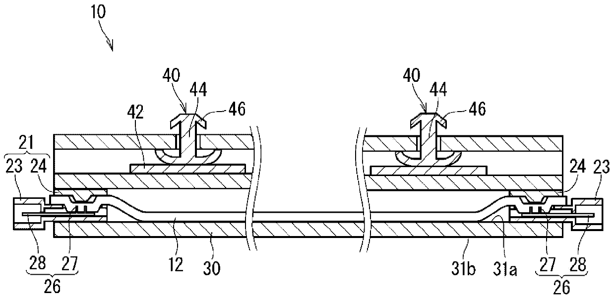
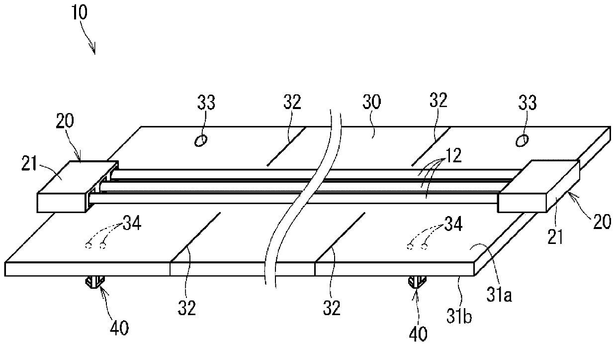
[0033] Hereinafter, the wire harness according to the embodiment will be described. figure 1 It is a perspective view which shows the wire harness 10 which concerns on embodiment. figure 2 It is a schematic cross-sectional view showing the wire harness 10 according to the embodiment. image 3 It is a perspective view showing the state before the exterior member 30 is rolled up. Figure 4 It is a bottom view showing the state before the exterior member 30 is rolled up.

[0034] The wire harness 10 is used as wiring for electrically connecting various electric devices mounted on a vehicle or the like. Here, the wire harness 10 will be described as a wire harness that is wired around an instrument panel in a vehicle, for example. Of course, the place where the wire harness 10 is routed in the vehicle is not limited to the above-mentioned places, and may be routed around the ceiling, the door, and the like. Specifically, the wire harness 10 ...


PUM


Abstract

The objective of the invention is to provide a technique capable of handling simply with one exterior member, both a region to be installed flat and a region to be installed bent in a wire harness. This wire harness comprises the exterior member formed into a sheet shape, and an electric wire laid in such a manner that a region in at least a portion along the extending direction thereof overlaps with the exterior member. At least a portion of the section over which the insulation cover of the electric wire overlaps with the exterior member is welded. A region in a portion of the exterior member along the extending direction of the electric wire is in a flat state. A region in at least another portion of the exterior member along the extending direction of the electric wire is curled in a direction intersecting the extending direction of the electric wire.

Description

technical field [0001] The present invention relates to a technique of attaching an exterior member to an electric wire in a wiring harness for a vehicle. Background technique [0002] Patent Document 1 discloses a technique of positioning the exterior member and the electric wire by wrapping a tape around each end of the exterior member and the electric wire extending from the end when assembling a sheet-shaped exterior member to the electric wire. [0003] prior art literature [0004] patent documents [0005] Patent Document 1: Japanese Patent Laid-Open No. 2015-72798 Contents of the invention [0006] The problem to be solved by the invention [0007] However, depending on the wire harness, some wire harnesses have a flatly arranged region and a curved arranged region. In this case, if different exterior components are attached to the flat area and the curved area, problems such as an increase in the number of parts will arise. In addition, when a single exterior...

Claims


Application Information

Patent Timeline
Patent Type & Authority Applications(China)
IPC IPC(8): H01B7/00B60R16/02
CPCH01B7/00B60R16/0215H02G3/30H02G3/34H02G3/0462H02G3/0456
Inventor 水野芳正平井宏树东小园诚石田英敏春日井正邦
Owner AUTONETWORKS TECH LTD
Learn More