Marine anchoring chain stopper

An anchoring and marine technology, applied in the direction of ships, etc., can solve the problems such as the lack of blocking blocks in the drum and the falling anchor of the iron chain, and achieve the effect of stable connection and convenient retraction of the iron chain.

Inactive Publication Date: 2021-07-23
江苏兴洋船舶设备制造有限公司
View PDF0 Cites 0 Cited by
  • Summary
  • Abstract
  • Description
  • Claims
  • Application Information

AI Technical Summary

Problems solved by technology

[0004] The purpose of the present invention is to provide a marine anchor chain stopper to solve the problem that the chain stopper la

Method used


Image

  • Marine anchoring chain stopper
  • Marine anchoring chain stopper
  • Marine anchoring chain stopper

Examples


Embodiment 1

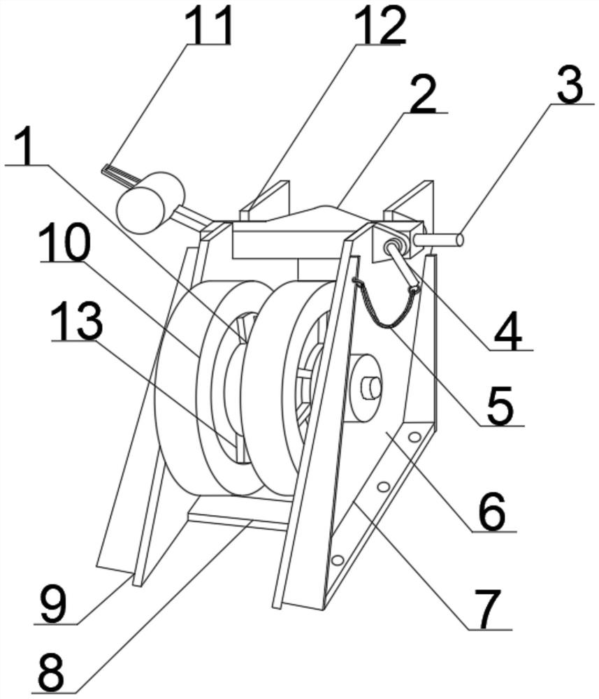
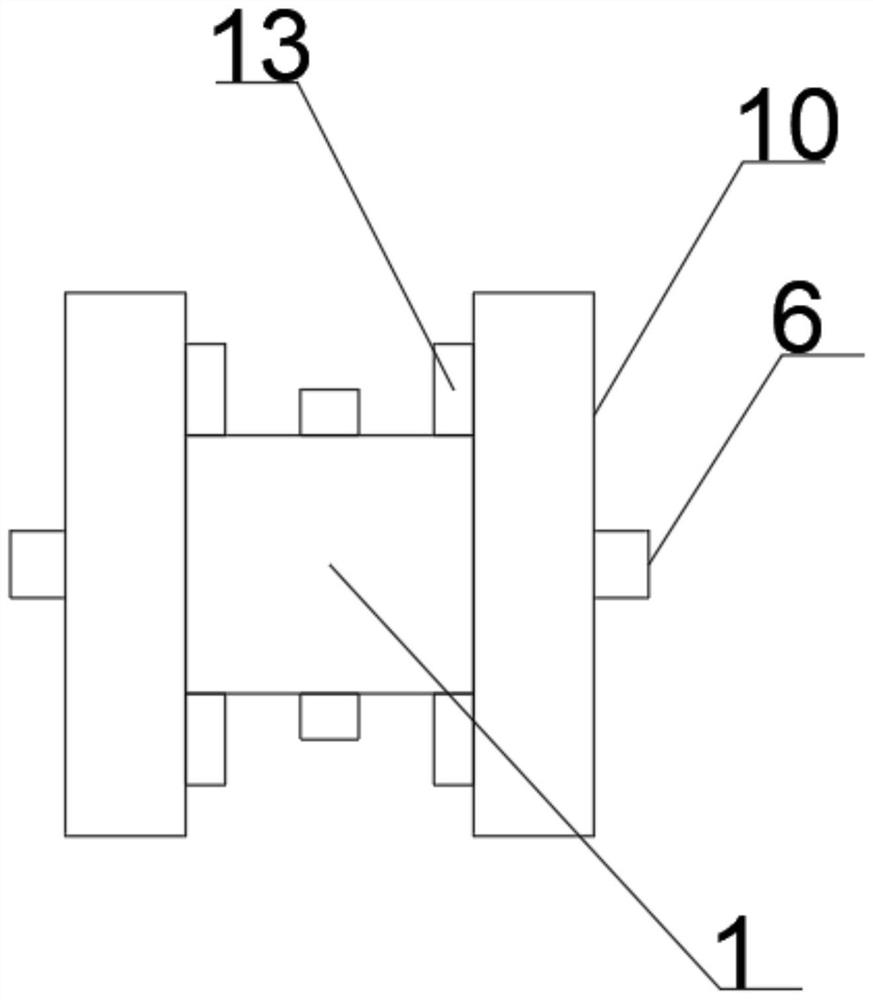
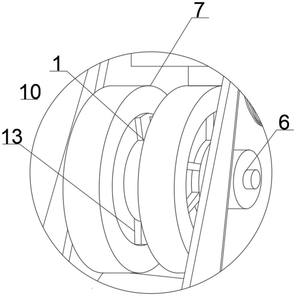
[0025] see figure 1 , figure 2 , image 3 , the present invention provides a technical solution: a marine anchoring chain stopper, comprising a chain stopper main body 7, a base 9 is provided at the lowermost position of the chain stopper main body 7, and a connection is provided at the right side of the base 9 Plate 8, a roller 10 is set on the upper side of the connecting plate 8, a roll 1 is set at the middle position on the right side of the roll 10, a block 13 is set at the outer side of the roll 1, and a block 13 is set at the middle position of the roll 1 There is a rotating shaft 6, a switch blade 2 is provided on the upper side of the roller 10, a notch 12 is provided at the connection position between the switch blade 2 and the base 9, a handle 11 is provided at the left side of the switch blade 2, and the switch blade 2 A handle 3 is provided at the right side of the handle 3, a hosel 4 is provided at the middle of the handle 3, a connection line 5 is provided at...

Embodiment 2

[0027] see figure 1 , figure 2 , image 3 , the present invention provides a technical solution: a marine anchor chain stopper, six blocks 13 are provided in total, and the six blocks 13 are respectively arranged at the outer positions of the reel 1, and the blocks 13 are connected through an integrated The method is connected with the reel 1, the rotating shaft 6 runs through the roller 10 and the reel 1, and the roller 10 and the reel 1 rotate on the main body 7 of the chain stopper through the rotating shaft 6, the hosel 4 runs through the switch knife 2, and the hosel 4. Fix the switch knife 2 on the main body 7 of the chain stopper. There are two bases 9 in total, and the two bases 9 are fixed on the ground by bolt connection.

[0028] The working principle and application process of the present invention: After the installation of the present invention is completed, support is provided by the base 9, and the base 9 is fixed on the hull by bolts, the iron chain can be ...


PUM


Abstract

A marine anchoring chain stopper disclosed in the invention comprises a chain stopper body, a base is arranged at the lowermost side position of the chain stopper body, a connecting plate is arranged at the right side position of the base, a rolling wheel is arranged at the upper side position of the connecting plate, a winding drum is arranged at the middle position of the right side of the rolling wheel, a clamping block is arranged on the outer side of the winding drum, a rotating shaft is arranged in the middle of the winding drum, a knife switch is arranged on the upper side of the rolling wheel, a notch is formed in the connecting position of the knife switch and the base, a handle is arranged on the left side of the knife switch, a handle is arranged on the right side of the knife switch, an inserting sheath is arranged in the middle of the handle, and an iron chain can be clamped on the winding drum through the clamping block, so the winding drum can be used for winding the iron chain more conveniently, and after the knife switch is put down, the iron chain can be pulled out slowly due to the fact that the iron chain is clamped on the clamping block, and the iron chain cannot fall down directly due to the weight.

Description

technical field [0001] The invention belongs to the technical field of a marine anchor chain stopper, in particular to a chain stopper. Background technique [0002] The chain stopper, also known as the chain stopper or the anchor chain stopper, refers to a special device for holding or clamping the anchor chain. It is fixed between the windlass and the chain barrel, and is separated from the chain wheel to withstand the anchor and mooring. The pulling force of the anchor and the anchor chain prevents it from being transmitted to the anchor chain wheel. The commonly used ones are the screw chain checker, the knife chain checker, the tongue type chain checker, the cam chain checker, the chain checker and the chain checker. Roller brake knife chain device, etc. [0003] The existing chain stopper for marine mooring has the following problems: when the current chain stopper is in use, there is no block on the drum, and after the switch knife is pulled up, the iron chain may di...

Claims


Application Information

Patent Timeline
IPC IPC(8): B63B21/18
CPCB63B21/18
Inventor 郑友勤申小强
Owner 江苏兴洋船舶设备制造有限公司
Why Eureka
Try Eureka