

Spinning bike for standing exercising
A spinning and sports technology, applied in sports accessories, training equipment for adjusting coordination, training equipment for adjusting cardiovascular system, etc., can solve the problems of easy fatigue, numbness of hands and wrists, etc. The effect of transportation and storage
- Summary
- Abstract
- Description
- Claims
- Application Information
AI Technical Summary
Problems solved by technology
Method used
Image

Examples
Embodiment 1
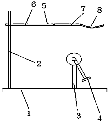
[0027] Embodiment 1: as figure 1 , 4 As shown, a spinning bicycle for standing exercise includes a base 1, an armrest bracket 2 on the base and a pedal bracket 3, the pedal bracket 3 is provided with a pedal 4, and the armrest bracket 2 is connected with an upper body support 5, The upper body support 5 comprises a support bar 6 and an arc plate 7 with a support bar hinge, the arc plate 7 is positioned above the pedal support 3, the arc plate 7 top is hinged with the support bar 6 ends, and the arc plate 7 is connected with the support bar. The ends of 6 are hinge points to rotate up and down, the curved plate 7 is wrapped with a soft bag, the two ends of the curved plate 7 are respectively connected with strips 8, and the free ends of the strips 8 at the two ends of the curved plate 7 are flexibly connected , The free ends of the strip belts 8 at both ends of the arc-shaped plate 7 are connected by buckles.
Embodiment 2
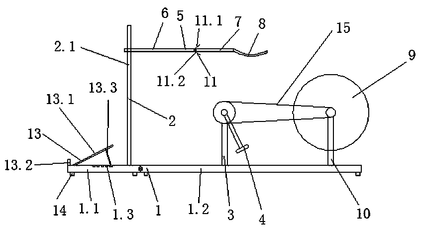
[0028] Embodiment 2: as figure 2 , 5 , shown in 6, a kind of spinning bicycle of standing motion, comprises base 1, is positioned at the armrest bracket 2 on the base and pedal bracket 3, is provided with pedal 4 on the pedal bracket 3, is connected with upper body support member on the armrest bracket 2 5. The upper body support 5 includes a support rod 6 and an arc-shaped plate 7 hinged with the support rod. The arc-shaped plate 7 is located above the pedal bracket 3. The top of the arc-shaped plate 7 is hinged with the end of the support rod 6. The arc-shaped plate 7 is connected with The end of the support rod 6 rotates up and down as a hinge point, and the end of the connection between the support rod 6 and the arc plate 7 is also provided with a limit plate 11. The limit plate 11 is divided into an upper limit plate 11.1 and a lower limit plate 11.2, and the arc plate 7 Rotate between the upper limit plate 11.1 and the lower limit plate 11.2. The curved plate 7 is wra...
Embodiment 3
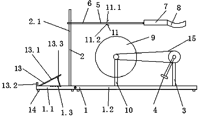
[0029] Embodiment 3: as image 3 , 5, shown in 6, a kind of spinning bicycle of standing motion, comprises base 1, is positioned at the armrest bracket 2 on the base and pedal bracket 3, is provided with pedal 4 on the pedal bracket 3, is connected with upper body support member on the armrest bracket 2 5. The upper body support 5 includes a support rod 6 and an arc-shaped plate 7 hinged with the support rod. The arc-shaped plate 7 is located above the pedal bracket 3. The top of the arc-shaped plate 7 is hinged with the end of the support rod 6. The arc-shaped plate 7 is connected with The end of the support rod 6 rotates up and down as a hinge point, and the end of the connection between the support rod 6 and the arc plate 7 is also provided with a limit plate 11. The limit plate 11 is divided into an upper limit plate 11.1 and a lower limit plate 11.2, and the arc plate 7 Rotate between the upper limit plate 11.1 and the lower limit plate 11.2. The curved plate 7 is wrapp...
PUM
 Abstract
Description
Claims
Application Information