Double-lane type battery replacement station

A power station and dual-lane technology, which is applied in vehicle maintenance, vehicle parts, electric power devices, etc., can solve the problems of low efficiency of battery replacement, low charging efficiency, and large area of ​​charging compartment, so as to reduce land use costs, The effect of improving the degree of automation and improving the efficiency of battery replacement

Pending Publication Date: 2019-10-15
BOZHON PRECISION IND TECH CO LTD
View PDF0 Cites 6 Cited by
  • Summary
  • Abstract
  • Description
  • Claims
  • Application Information

AI Technical Summary

Problems solved by technology

[0004] Most of the existing battery swapping stations use a layout mode in which one charging bin corresponds to a group of guiding and positioning lanes or two or more charging bins correspond to a group of guiding and positioning lanes. Because the charging bin not only undertakes the charging function of the battery, but also undertakes the storage of the battery. This makes the charging warehouse often occupy a large area, which leads to the following problems in the existing power station: First, the utilization rate of a single charging warehouse is low, which makes the land utilization rate low and improves the equipment. cost and land cost; secondly, it takes too much time for the battery to be docked with the charging plug in the battery compartment, resulting in low charging efficiency; thirdly, during the battery replacement process, the battery frequently enters and exits the charging compartment, and the existing charging compartment Lack of fast and accurate positioning of the battery; finally, the automation of the battery replacement process is low, resulting in low battery replacement efficiency

Method used


Image

  • Double-lane type battery replacement station
  • Double-lane type battery replacement station
  • Double-lane type battery replacement station

Examples


Embodiment Construction

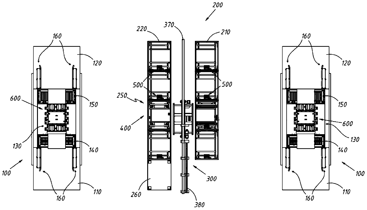
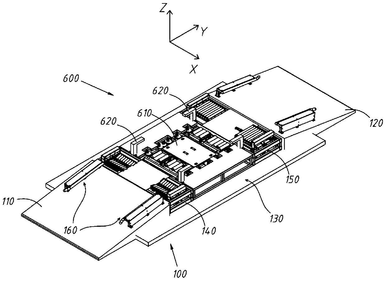
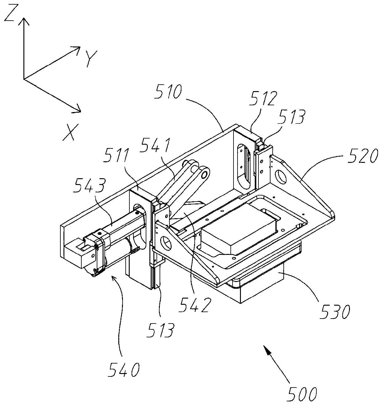
[0093] The present invention will be further described in detail below in conjunction with the accompanying drawings, and the aforementioned and other objects, features, aspects and advantages of the present invention will become more apparent, so that those skilled in the art can implement them with reference to the description.

[0094] In the drawings, the shapes and dimensions may be exaggerated for clarity, and the same reference numerals will be used throughout to designate the same or like parts.

[0095] In the following description, terms such as center, thickness, height, length, front, back, rear, left, right, top, bottom, upper, lower, etc. are defined with respect to the configuration shown in each drawing , in particular, "height" is equivalent to the dimension from top to bottom, "width" is equivalent to the dimension from left to right, and "depth" is equivalent to the dimension from front to back. They are relative concepts, so it may be based on It changes co...


PUM


Abstract

The invention discloses a double-lane type battery replacement station, which comprises two groups of guiding positioning lanes arranged oppositely and at an interval and a charging chamber arranged between the two groups of guiding positioning lanes. The charging chamber comprises: a first charging rack; and a second charging rack, which is opposite to the first charging rack and at an interval in order to form a conveying channel between the first charging rack and the second charging rack. A stacker crane for taking and placing batteries is disposed in the conveying lane, and at least one battery conveying trolley, which moves back and forth between the stacker crane and the guiding positioning lane, is arranged between the stacker crane and the guiding positioning lane. According to the invention, the double-lane layout is adopted, the charging and storage capacity of the single group of charging chamber can be fully utilized, the battery replacement efficiency is improved, and theequipment cost and the land use cost are reduced; the movement stroke of the charging connector is improved to improve the butt joint efficiency, and meanwhile, the capacity of the charging chamber for accommodating the batteries is greatly improved; the automation degree of the battery replacement process is improved, and the battery replacement efficiency is further improved.

Description

technical field [0001] The invention relates to the field of electric vehicles, in particular to a two-lane battery-swapping station. Background technique [0002] The process of battery replacement with a full battery is a fast charging method for electric vehicles. Specifically, it refers to replacing the battery of an electric vehicle with a battery replacement device and immediately replacing it with a fully charged battery. The place where the battery of the electric vehicle is fully discharged. [0003] In the process of battery swapping for an electric vehicle with a fully depleted battery, it is necessary to first drive the electric vehicle with insufficient power into the guidance and positioning lane, then remove the depleted battery from the vehicle, and at the same time take out the fully charged battery from the charging compartment to replace it In the car, the replaced battery needs to be placed in the charging compartment for charging for recycling. [0004...

Claims


Application Information

Patent Timeline
Patent Type & Authority Applications(China)
IPC IPC(8): B60S5/06
CPCB60S5/06
Inventor 戴有发牟东肖申叶庆丰孙庆吴小平
Owner BOZHON PRECISION IND TECH CO LTD
Why Eureka
Try Eureka