Arrangement for guiding car cable

A cable and cable connection technology, applied in the field of car cable installation, can solve the problems of difficult maintenance and high cost

Inactive Publication Date: 2003-03-19
KONE CORP
View PDF2 Cites 0 Cited by
  • Summary
  • Abstract
  • Description
  • Claims
  • Application Information

AI Technical Summary

Problems solved by technology

However, this solution requires a car cable suitable for the purpose and a special starting device along the entire length of the cable in the elevator shaft
This solution is expensive and difficult to maintain

Method used


Image

  • Arrangement for guiding car cable
  • Arrangement for guiding car cable
  • Arrangement for guiding car cable

Examples


Embodiment Construction

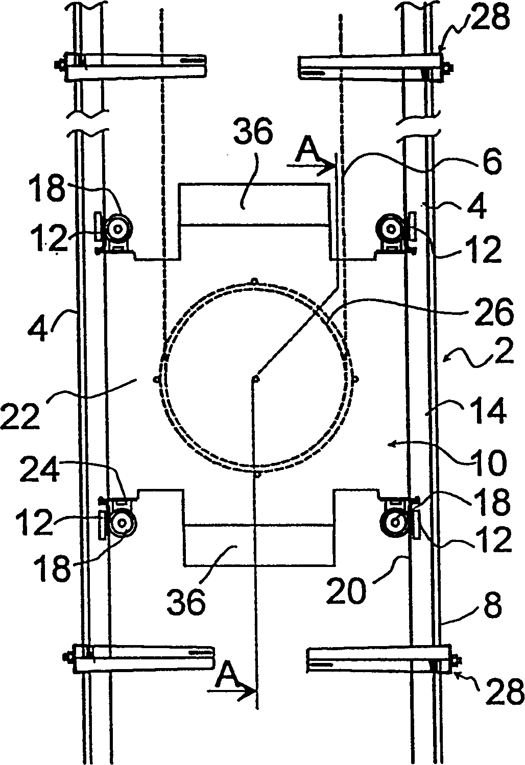
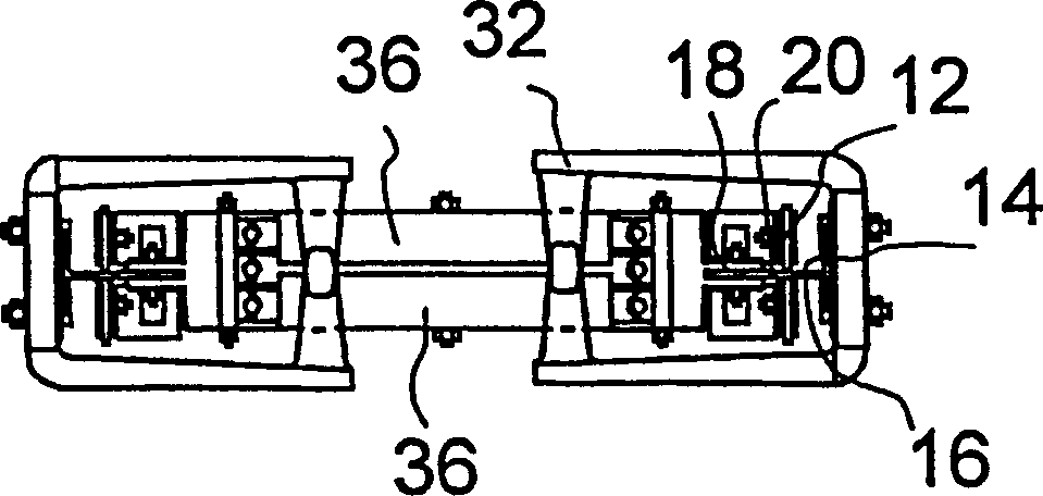
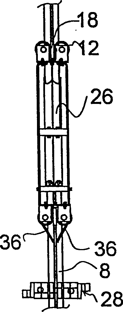
[0015] figure 1 , 2 and 3 illustrate an elevator car cable guide installed in an elevator shaft 2 according to the invention. One end of the car cable 6 is connected to an elevator car (not shown) and the other end is connected to a connection point (not shown) in the elevator shaft in the middle or higher between the two ends of the shaft. The car cable is suspended between its two connection points in a loop, the lowest point of which follows the movement of the elevator car. A cable guide beam 4 is placed in the elevator shaft 2 extending from the bottom of the shaft 2 over a distance corresponding to the length of the car cable 6 . The guide beam 4 is a T-beam connected at its base 8 to the shaft by guide beam brackets (not shown) located at a suitable distance. The sides of the shaft of the guide beam 4 form guide planes 14 and 16 for the guide roller 12 . Guide rollers 18 move along the edge 20 of the shaft. As from the front ( figure 1 ) As seen, the carriage 10 f...


PUM


Abstract

Arrangement for guiding a car cable (6), one end of said car cable (6) being attached to the elevator car while the other end is attached to a connection point in the elevator shaft. The car cable (6) forms a loop hanging below its points of attachement. The arrangement comprises at least one cable holder (28). The cable portion between the attachment point and the lowest point of the cable loop can be held by the cable holder (28) so as to limit the lateral motion of the cable (6).

Description

technical field [0001] The invention relates to a device for guiding car cables of an elevator. Background technique [0002] The elevator car is connected to the outside space by means of a car cable, which is used for the electrical supply of the elevator car and for the transmission of information between the car signaling devices, such as display devices and call buttons, and the elevator control system. One end of the car cable is connected at a suitable place in the elevator shaft and the other end is connected to the bottom of the elevator car or car frame. The car cables hang freely in the shaft or in taller buildings, supported together with tensioning weights. [0003] In high-rise buildings, the elevator shaft can be hundreds of meters long, thus the car cables can have a length of tens of meters and tend to oscillate despite tensioned counterweights. In tall buildings, sway is produced by the movement of the elevator and its resulting air currents and by shakin...

Claims


Application Information

Patent Timeline
Patent Type & Authority Patents(China)
IPC IPC(8): B66B7/06
CPCB66B7/06
Inventor 约翰尼斯·德琼
Owner KONE CORP
Why Eureka
Try Eureka