Fabricated self-reset U-shaped metal damper

A metal damper and self-resetting technology, which is applied in building types, protected buildings/shelters, buildings, etc., can solve the problem of lack of self-resetting ability, energy-consuming components, structural stress and use functions that are difficult to repair and self-resetting Small capacity and other problems, to achieve the effect of convenient and efficient installation and disassembly, simple structure and stable performance

Inactive Publication Date: 2019-10-15
HAINAN UNIVERSITY
View PDF7 Cites 6 Cited by
  • Summary
  • Abstract
  • Description
  • Claims
  • Application Information

AI Technical Summary

Problems solved by technology

[0004] However, there are still many defects in the design and performance of U-shaped metal dampers used for energy dissipation and shock absorption. Among them, one of the more common defects is: the damper produces yield deformation during the energy dissipation process, and after the energy dissipation ends , due to t

Method used


Image

  • Fabricated self-reset U-shaped metal damper

Examples


Embodiment 1

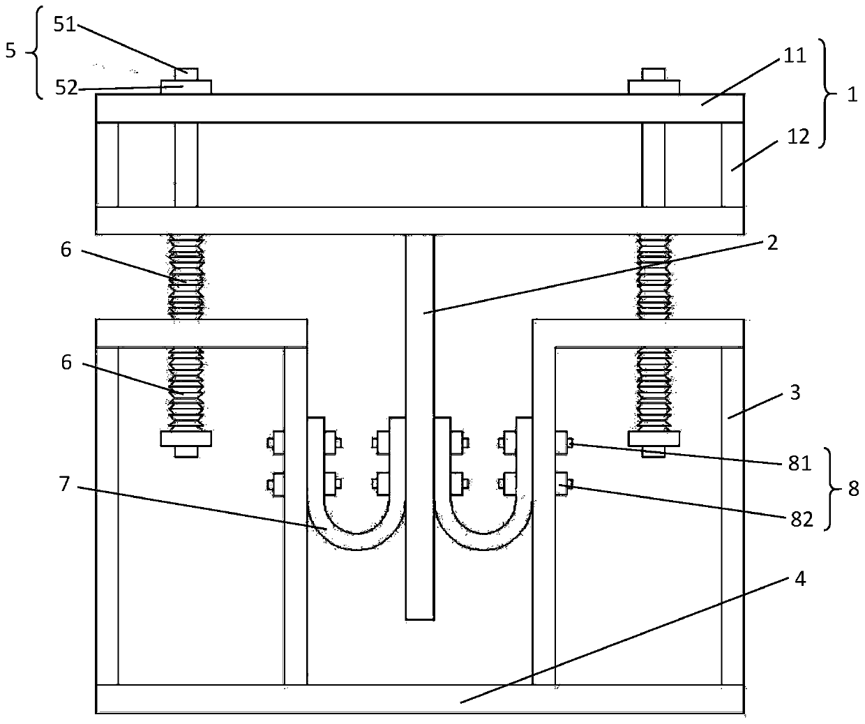
[0071] See attached figure 1 , the embodiment of the present invention discloses an assembled self-resetting U-shaped metal damper, including: a steel plate composite member 1, a piston member 2, a box-shaped member 3, a bottom plate 4, a fastener 5, an elastic member 6 and a U-shaped plate 7;

[0072] The steel plate composite member 1 includes a flange plate 11 and a web 12; two flange plates 11 are arranged in parallel up and down; a plurality of web plates 12 are fixed between the two flange plates 11;

[0073] The piston member 2 is fixedly connected to the center of the bottom surface of the lower flange plate 11;

[0074] The box-shaped member 3 is a box-shaped structure with two ends open or closed, and a plurality of box-shaped members 3 are arranged around the piston member 2;

[0075] The bottom plate 4 serves as the common bottom of a plurality of box-shaped components 3;

[0076] Fastener 5 fits through the top plate of two flange plates 11 and box-shaped membe...

Embodiment 2

[0091] The difference between this embodiment and Embodiment 1 is that the piston member 2 is a triangular box-shaped structure composed of three steel plates, the number of box-shaped members 3 and U-shaped plates 7 are three, and the box-shaped members 3 are respectively located in three On the outside of each steel plate, U-shaped plates 7 are respectively located between each steel plate and the box-shaped member 3 .

[0092] Other structures and working principles of this embodiment are the same as those of Embodiment 1, and will not be repeated here.

Embodiment 3

[0094] The difference between this embodiment and Embodiment 1 is that the piston member 2 is a rectangular box-shaped structure composed of four steel plates, the number of box-shaped members 3 and U-shaped plates 7 are four, and the box-shaped members 3 are respectively located on four On the outside of each steel plate, U-shaped plates 7 are respectively located between each steel plate and the box-shaped member 3 .

[0095] Other structures and working principles of this embodiment are the same as those of Embodiment 1, and will not be repeated here.


PUM


Abstract

The invention discloses a fabricated self-reset U-shaped metal damper. The metal damper comprises a steel plate composite component, a piston component, a box component, a bottom plate, a fastener, anelastic component and a plurality of U-shaped plate; the steel plate composite component comprises a flange plate and a web; two side plates of the U-shaped plates are fastened to a side plate of thepiston component and a side plate of the box component through a plurality of connecting members; the U-shaped plates enter an elastoplastic yielding state when vibrating, hysteresis is generated, and energy is consumed. According to the damper provided by the invention, the deformation energy consumption performance of the U-shaped plates can be adjusted according to different working conditionsthrough disassembly and replacement; metal has good hysteresis characteristics after entering the plastic state, and absorb a large amount of energy in the elastoplastic hysteresis deformation process, and the metal can provide additional damping and rigidity for the structure when being used as an energy-consuming device; and meanwhile, the damper components can be can be disassembled and replaced in time after fatigue fracture, the energy consumption effect is good, and the self-reset ability is high.

Description

technical field [0001] The invention relates to the technical field of energy dissipation and shock absorption, and more specifically relates to an assembled self-resetting U-shaped metal damper. Background technique [0002] In recent years, many relatively large earthquakes have taken place at home and abroad, causing great casualties and property losses. Earthquake disasters have become one of the most serious natural disasters faced by human beings. The traditional anti-seismic mainly relies on the deformation and energy consumption of the building itself to resist the seismic force, and this anti-seismic method will cause irreparable damage to the building. For decades, after continuous research by domestic and foreign scholars, it is proposed to add a damper to the building, and use the energy-dissipating element of the damper to absorb the energy input into the structure by the earthquake, thereby protecting the main load-bearing components of the building, that is, p...

Claims


Application Information

Patent Timeline
IPC IPC(8): E04B1/98E04H9/02
CPCE04H9/021E04H9/0235
Inventor 陈云罗祥
Owner HAINAN UNIVERSITY
Why Eureka
Try Eureka