Navigable wave power generation device

A power generation device and wave power generation technology, applied in ocean energy power generation, transportation and packaging, engine components, etc., can solve the problems of high cost of ocean engineering, high towage resistance, high manufacturing cost, etc., and achieve strong wind and wave resistance and stability Good, the effect of increasing the installed capacity

Inactive Publication Date: 2019-10-15
中科鑫源生态环境科技(广东)有限公司
View PDF0 Cites 4 Cited by
  • Summary
  • Abstract
  • Description
  • Claims
  • Application Information

AI Technical Summary

Problems solved by technology

However, although the draft of the rear bend pipe device is relatively shallow, simple, and has high conversion efficiency, it requires a tugboat for marine construction, and the towing resistance is large during towing, and the stability of the device is poor. The installed capacity of a single machine is limited.
[0006] At present, both floating floating oscillating water column technology and floating wave surfing technology have the characteristics of high manufacturing cost and high cost of ocean engineering. The floating oscillating water column technology has simple structure, low cost and high conversion efficiency, but the ocean engineering cost of towing is high. The stability of the device is poor, and the installed capacity of a single unit is limited, so that the technology of using wave power generation cannot be popularized

Method used


Image

  • Navigable wave power generation device
  • Navigable wave power generation device
  • Navigable wave power generation device

Examples


Embodiment Construction

[0027] In order to facilitate the understanding of the present invention, the present invention will be described more fully below with reference to the relevant drawings.

[0028] It should be noted that when an element is considered to be "connected" to another element, it may be directly connected to and integrally integrated with the other element, or there may be an intervening element at the same time. The terms "mounted", "one end", "the other end" and similar expressions are used herein for the purpose of description only.

[0029] Unless otherwise defined, all technical and scientific terms used herein have the same meaning as commonly understood by one of ordinary skill in the art. The terminology used in the description herein is only for the purpose of describing specific embodiments, and is not intended to limit the present invention. As used herein, the term "and / or" includes any and all combinations of one or more of the associated listed items.

[0030] Such ...


PUM


Abstract

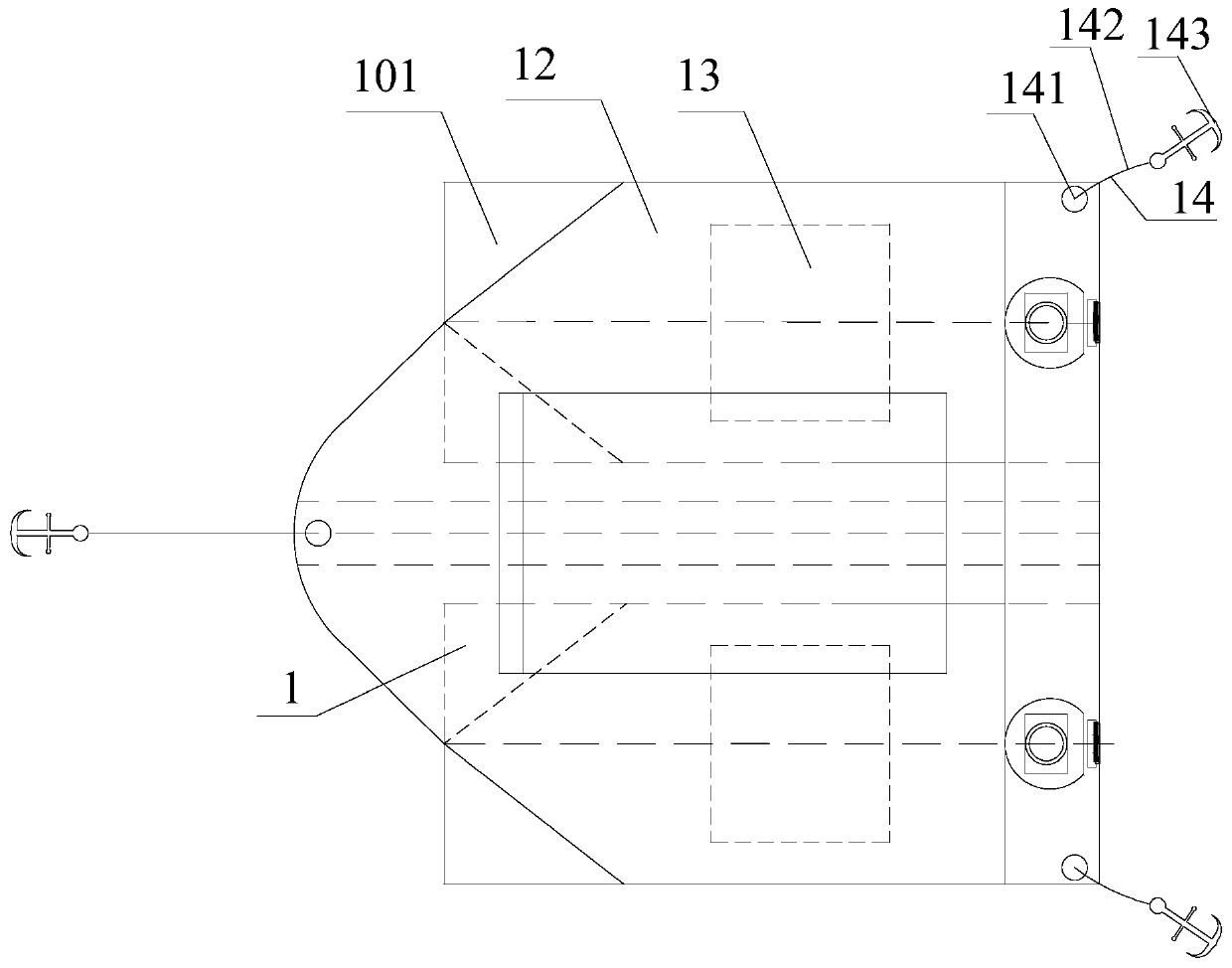
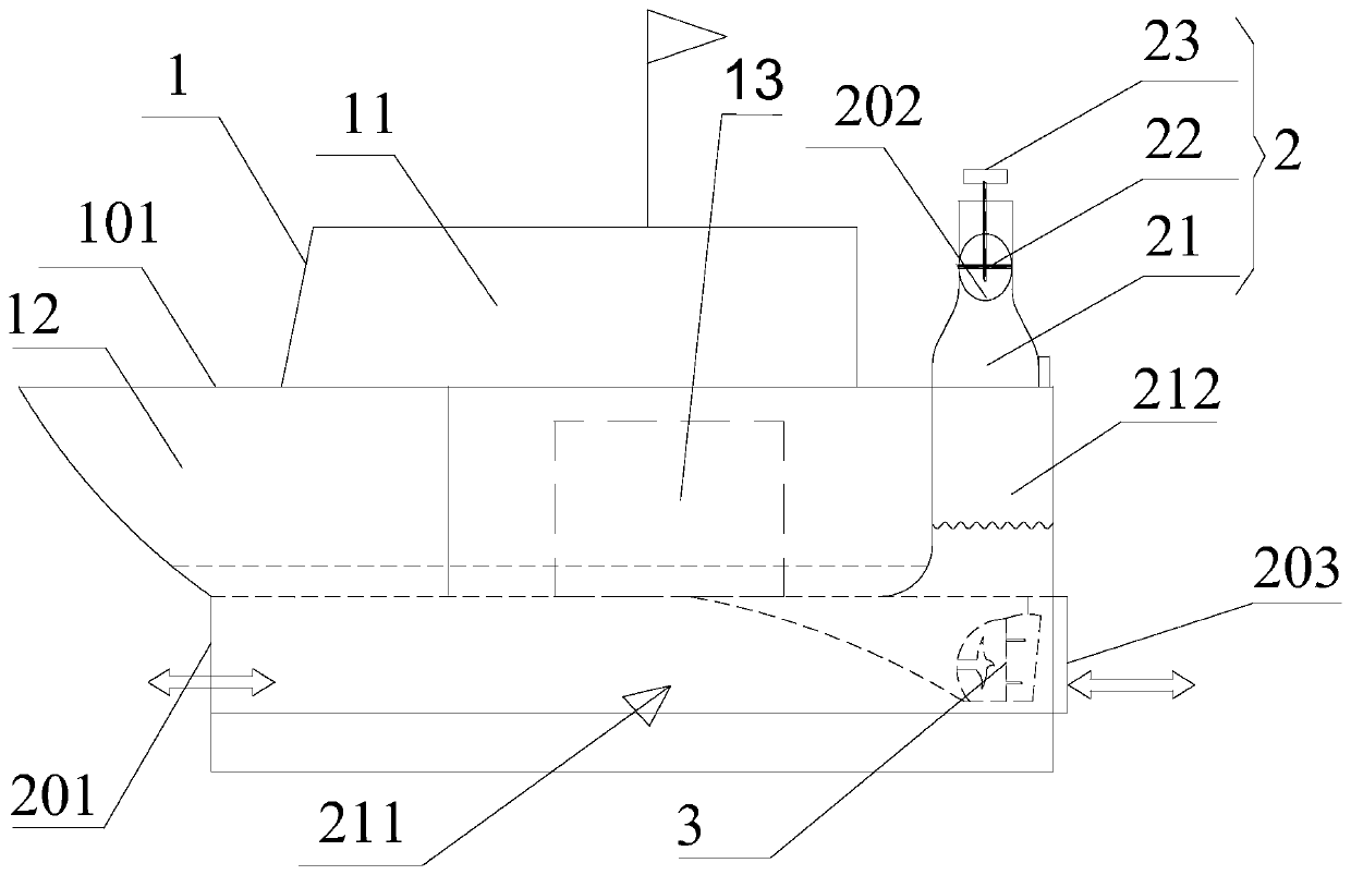
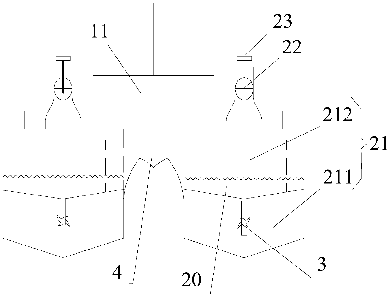
The invention provides a navigable wave power generation device. The navigable wave power generation device comprises a composite hull and a driving mechanism arranged on the composite hull, wherein the composite hull comprises a plurality of single hulls, and the adjacent single hulls are connected with one another. The navigable wave power generation device is characterized in that at least twosingle hulls are each provided with a wave power generation mechanism, and each wave power generation mechanism comprises a fluid chamber, an air turbine and a generator, wherein the fluid chamber islocated on the corresponding single hull; the fluid chamber comprises an inlet, an outlet and an auxiliary outlet; the inlet is positioned at the lower part of the single hull and faces the forward direction of the composite hull, the auxiliary outlet is also positioned at the lower part of the single hull but is opposite to the forward direction of the composite hull; a gate controlling the opening and closing of the auxiliary outlet is arranged on the auxiliary outlet, the outlet is connected with the air turbine, and the generator is connected with the air turbine. The navigable wave powergeneration device has the advantages of large installed capacity, high stability, high efficiency, low ocean engineering cost and low investment.

Description

technical field [0001] The invention relates to the technical field of wave energy conversion, in particular to a navigable wave power generation device. Background technique [0002] Wave energy resources are abundant and have great potential for development and utilization. However, the cost of developing and utilizing ocean wave energy is high due to factors such as extremely unstable wave energy, distance from the mainland, harsh ocean environment, seawater corrosion, and marine organisms. These costs are mainly reflected in the material cost, construction cost, conversion mechanism cost, launch, transportation and recovery cost, anchoring cost, maintenance cost and environmental cost of the device. At present, there are many types of wave energy utilization technologies, and the floating wave energy utilization technology has become the mainstream of research because of its wide adaptability. The mainstream floating technologies mainly include three categories: oscilla...

Claims


Application Information

Patent Timeline
Patent Type & Authority Applications(China)
IPC IPC(8): F03B13/24B63B35/44B63H19/04
CPCB63B35/44B63B2035/4466B63H19/04F03B13/24F05B2220/706Y02E10/30Y02T70/5236
Inventor 吴亨宇吴必军
Owner 中科鑫源生态环境科技(广东)有限公司
Why Eureka
Try Eureka