Supercharge Your Innovation With Domain-Expert AI Agents!

Novel fluid supercharger

A turbocharger and fluid technology, which is applied in the direction of fluid pressure converters, mechanical equipment, etc., can solve the problems of low working efficiency and energy consumption of compressors

Pending Publication Date: 2019-10-15
封海涛
View PDF0 Cites 0 Cited by
  • Summary
  • Abstract
  • Description
  • Claims
  • Application Information

AI Technical Summary

Problems solved by technology

[0003] In order to solve the problems of energy consumption and low working efficiency of the compressor, a fluid booster with a new structure is designed

Method used


Image

  • Novel fluid supercharger
  • Novel fluid supercharger

Examples


Embodiment

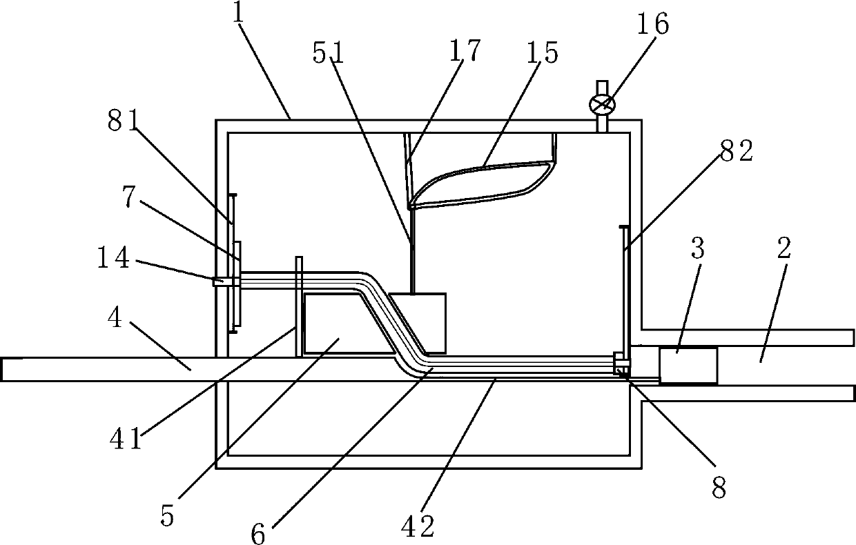
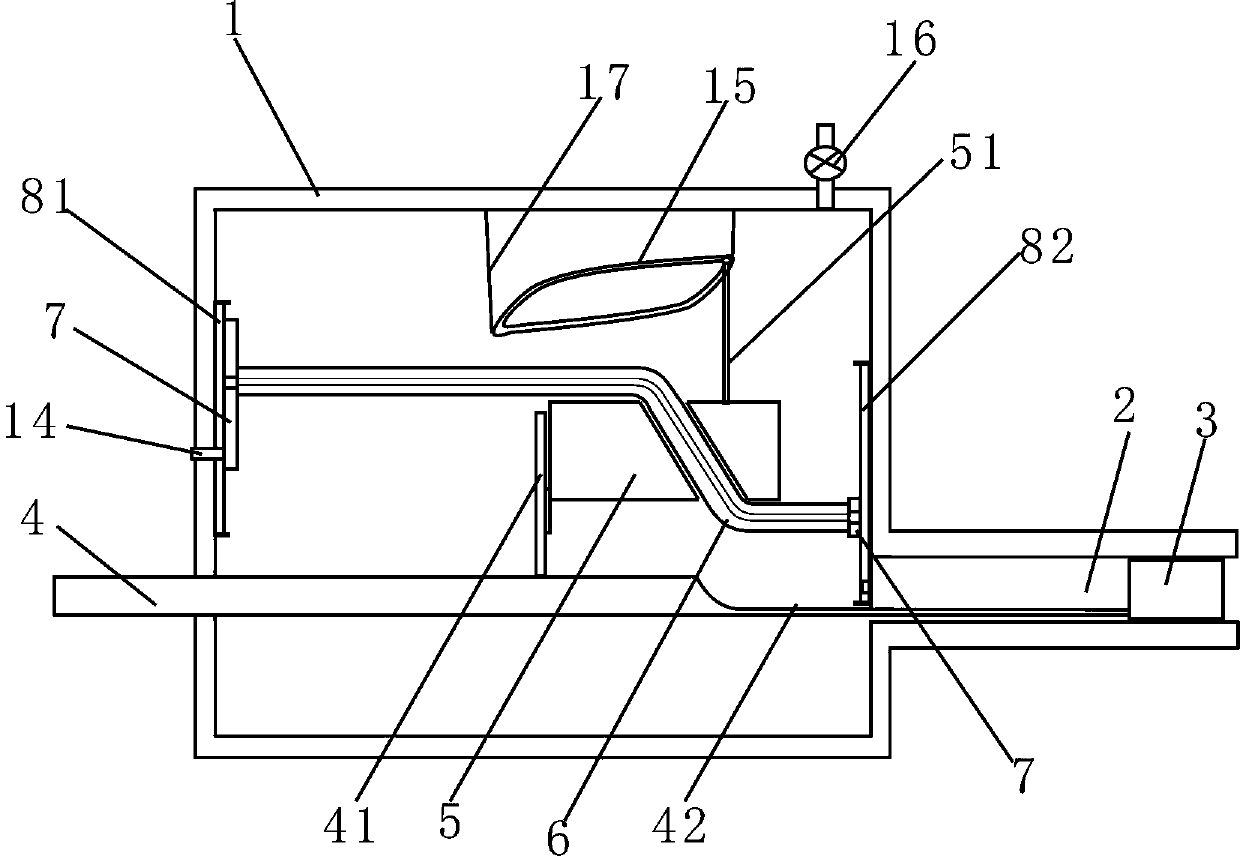
[0016] Embodiment: a kind of novel fluid booster, as figure 1 , figure 2 As shown, it is composed of a high-pressure fluid tank 1, a cylinder 2, a piston 3, a piston rod 4, a moving slider 5 and a flexible rod 6. One end of the high-pressure fluid tank 1 communicates with the left side of the cylinder 2. A piston 3 is installed in the cylinder 2. The piston 2 is connected to the piston rod 4. The piston rod 4 runs through the high-pressure fluid tank 1 and is connected to the piston in the cylinder 2. The end of the piston rod 4 is located at the high-pressure Outside the fluid tank 1, the end of the piston rod 4 is connected to an engine or a telescopic power mechanism to drive the piston rod to do telescopic movement. The high-pressure fluid tank 1 is provided with an output gas port 16 with a valve for outputting high-pressure fluid to the outside.

[0017] The moving slider 5 is installed in the high-pressure fluid tank 1, and the left end is connected with the slider c...


PUM


Abstract

The invention relates to a novel fluid supercharger. The novel fluid supercharger comprises a high-pressure fluid tank, a cylinder, a piston, a piston rod, a movable slide block and a flexible rod; one end of the high-pressure fluid tank communicates with the left side of the cylinder; the piston is connected with the piston rod; the piston rod penetrates through the high-pressure fluid tank, andis connected with the piston in the cylinder; the tail end of the piston rod is positioned at the external of the high-pressure fluid tank; the movable slide block is mounted in the high-pressure fluid tank, and the left end is connected with a slide block chute fixed in the piston rod; the movable slide block slides up and down in the slide block chute; an inclined hole is formed in middle of themovable slide block; the flexible rod is inserted in the inclined hole; the left and right ends of the flexible rod are connected with the left and right side walls of the high-pressure fluid tank; and a flexible rod groove is formed in the piston rod for placing the flexible rod. The piston rod moves to the left side; the piston presses fluids in the left side of the cylinder into the high-pressure fluid tank; the piston rod pulls the movable slide block to the left side; and under limiting by a trajectory of an annular slide block guide rail, the movable slide block moves down at the same time, and is returned to an initial state when reaching the most left side to finish once fluid supercharging.

Description

technical field [0001] The invention relates to a machine for compressing or boosting air and fluid, in particular to a novel fluid booster. Background technique [0002] The existing air compressor first sucks in external air, and then compresses the air into a high-pressure air tank through piston compression, and performs the compression work in a cycle. The compression work efficiency is low and the energy consumption is large. And the compression between gas and liquid cannot be used universally. Contents of the invention [0003] In order to solve the problems of energy consumption and low working efficiency of the compressor, a fluid booster with a new structure is designed. [0004] A new type of fluid booster, including a high-pressure fluid tank, a cylinder, a piston, a piston rod, a moving slider and a flexible rod, one end of the high-pressure fluid tank communicates with the left side of the cylinder, a piston is installed in the cylinder, and the piston is c...

Claims


Application Information

Patent Timeline
IPC IPC(8): F15B3/00
CPCF15B3/00
Inventor 封海涛
Owner 封海涛
Features
  • R&D
  • Intellectual Property
  • Life Sciences
  • Materials
  • Tech Scout
  • Unparalleled Data Quality
  • Higher Quality Content
  • 60% Fewer Hallucinations
Learn More