
Clamp

A technology of fixtures and jaws, which is applied in the field of fixtures and can solve problems such as low work efficiency of fixtures

Active Publication Date: 2018-12-14
GREE ELECTRIC APPLIANCES INC +1
View PDF11 Cites 6 Cited by
  • Summary
  • Abstract
  • Description
  • Claims
  • Application Information

AI Technical Summary

Problems solved by technology

[0004] The main purpose of the present invention is to provide a clamp to solve the problem of low work efficiency of clamps in the prior art

Method used


Image

  • Clamp
  • Clamp
  • Clamp

Examples


Embodiment Construction

[0023] It should be noted that, in the case of no conflict, the embodiments in the present application and the features in the embodiments can be combined with each other. The present invention will be described in detail below with reference to the accompanying drawings and examples.

[0024] It should be noted that, unless otherwise specified, all technical and scientific terms used in this application have the same meaning as commonly understood by those of ordinary skill in the art to which this application belongs.

[0025] In the present invention, in the absence of a contrary statement, the used orientation words such as "up and down" usually refer to the direction shown in the drawings, or refer to the vertical, vertical or gravity direction Similarly, for the convenience of understanding and description, "left and right" usually refer to the left and right shown in the drawings; The words are not used to limit the invention.

[0026] In order to solve the problem of...


PUM


Abstract

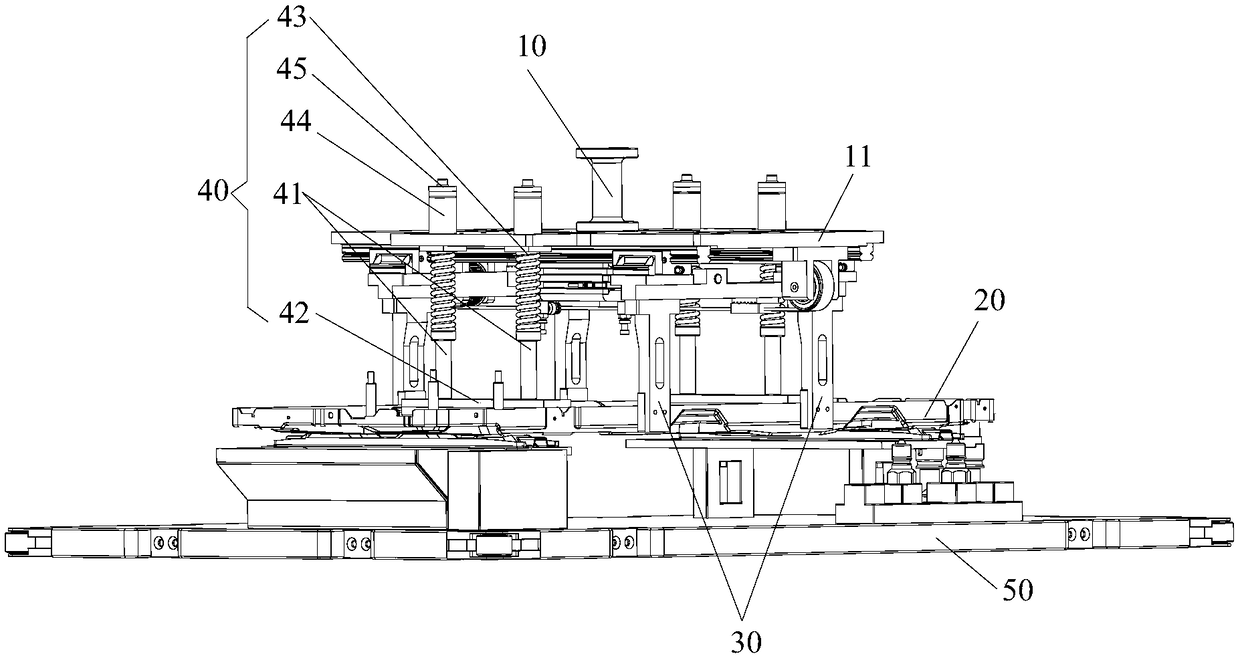
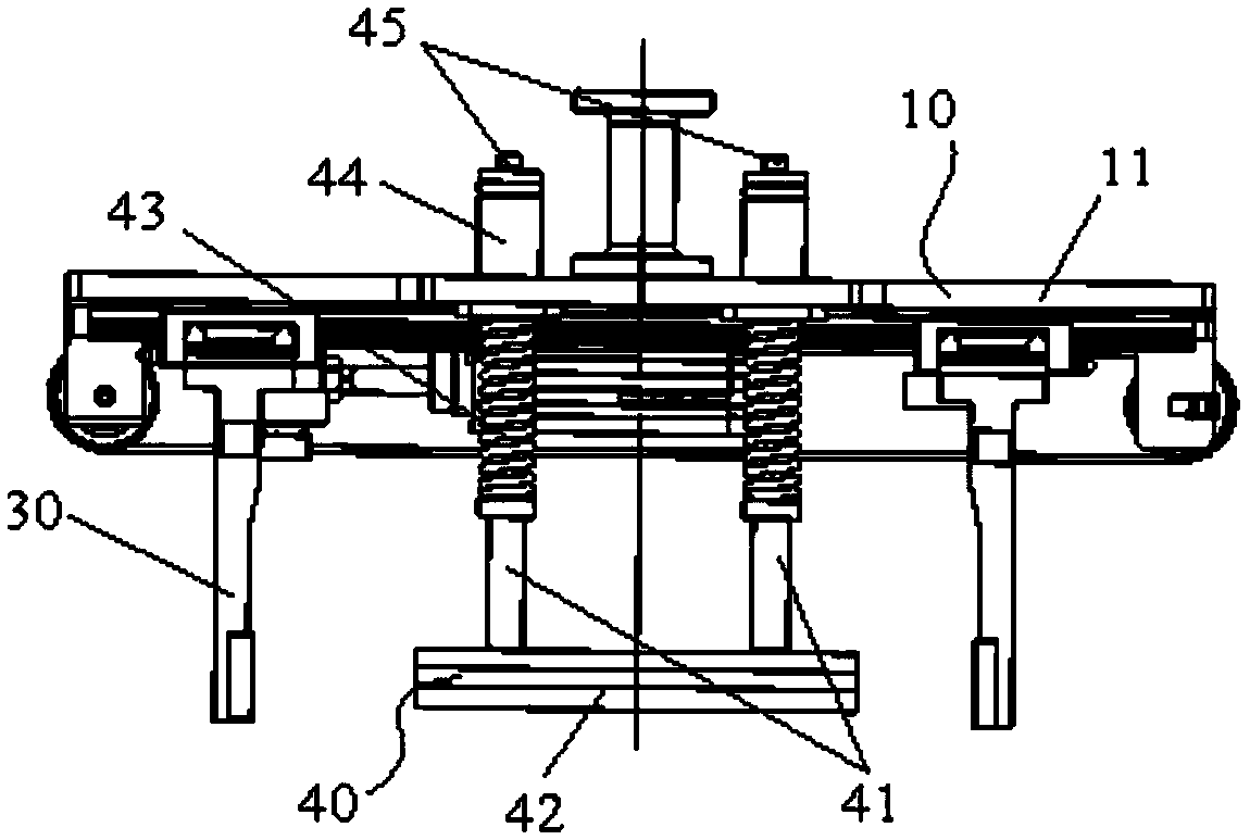
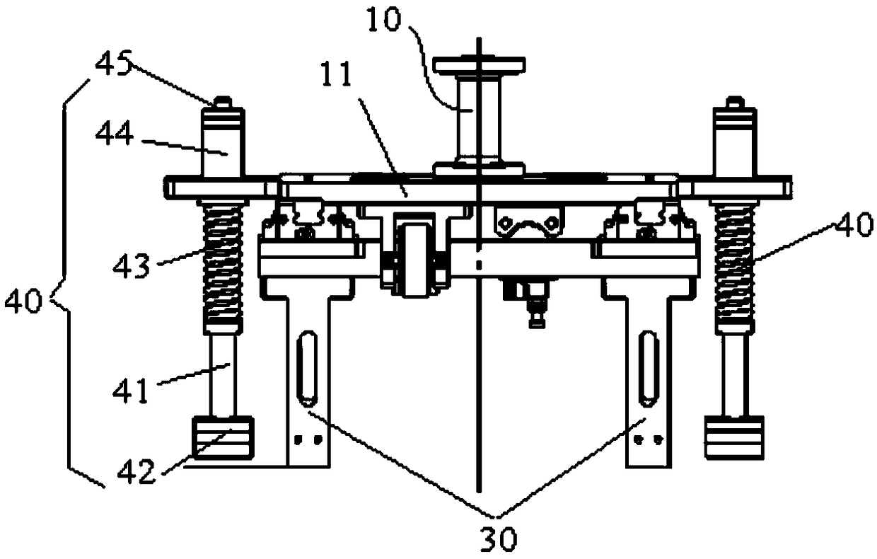
The invention provides a clamp. The clamp is used for assembling a clamped part and a part to be assembled together. The clamp comprises a clamp body, a clamping jaw and a tightly-pressing assembly, wherein the clamping jaw is used for clamping the clamped part, the clamping jaw is movably arranged on the clamp body; and the tightly-pressing assembly is arranged on the clamp body, and at least part of the tightly-pressing assembly is telescopically arranged to enable the tightly-pressing assembly to apply acting force towards the part to be assembled to the clamped part after the clamping clawplaces the clamped part on the part to be assembled so as to press the clamped part tightly on the part to be assembled. The clamp effectively solves the problem of low working efficiency of a clampin the prior art.

Description

technical field [0001] The present invention relates to the technical field of clamps, in particular to a clamp. Background technique [0002] At present, the chassis of the external unit of the air conditioner is stamped from sheet metal. During the stamping process of the sheet metal, the sheet metal is easily deformed due to force or other thermal effects, or the hole after sheet metal stamping is caused by other unavoidable factors. Bits are slightly off. Due to the above-mentioned processing method of the chassis, in the process of assembling the external unit of the air conditioner, it is easy to happen that the positioning holes of the chassis cannot be assembled with the pins on the craft board due to burrs, that is, the pins cannot be fully inserted into the positioning holes, which affects The assembly quality of the chassis and the process board is improved. [0003] In the prior art, traditional clamps are mainly used to clamp and place the chassis. However, t...

Claims


Application Information

Patent Timeline
IPC IPC(8): B23P19/00B25B11/02
CPCB23P19/00B25B11/02
Inventor 武云志谭畅莫玉麟蒋乾坤郑海强
Owner GREE ELECTRIC APPLIANCES INC
Learn More