A Synchronous Laser Radar Optical System for Transmitting and Receiving

A laser radar and optical system technology, applied in the direction of radio wave measurement systems, instruments, measuring devices, etc., can solve the problems of inaccurate test results, inability to accurately guarantee the synchronous rotation of two sets of vibrating mirrors, and unsynchronized vibrating mirrors, etc., to achieve simplification The design difficulty is completely consistent with the structure and phase, and the effect of reducing the viewing angle

Active Publication Date: 2021-10-22
XI AN ZHISENSOR TECH CO LTD
View PDF8 Cites 0 Cited by
  • Summary
  • Abstract
  • Description
  • Claims
  • Application Information

AI Technical Summary

Problems solved by technology

[0009] In order to solve the problem of inaccurate test results caused by the inability to accurately guarantee the synchronous rotation of the two sets of vibrating mirrors and the fact that the coaxial optical system for transmitting and receiving is likely to reflect the emitted stray light into the photodetector, the present invention proposes a new optical system for transmitting and receiving synchronous laser radar. system
The surface of the vibrating mirror or the rotating motor is divided into two parts, the upper and lower parts, which are completely isolated. After the laser is collimated, it is reflected by the surface of the upper part to form a laser radar transmitting system; the surface of the lower part reflects the echo energy back to the detector to form a laser radar receiving system. While transmitting and receiving synchronous optical system, the problem of out-of-synchronization of the galvanometer is solved, and the reliability of the test results is improved.

Method used


Image

  • A Synchronous Laser Radar Optical System for Transmitting and Receiving
  • A Synchronous Laser Radar Optical System for Transmitting and Receiving
  • A Synchronous Laser Radar Optical System for Transmitting and Receiving

Examples


Embodiment 1

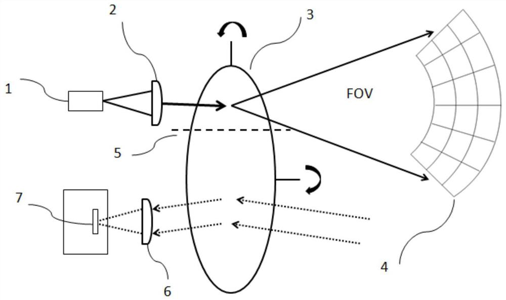
[0036] From figure 1 It can be seen that the laser radar optical system for transmitting and receiving synchronously in this embodiment includes a laser radar transmitting system and a laser radar receiving system. The laser radar transmitting system includes a pulse laser 1, a collimating lens group 2, and a two-dimensional MEMS vibrating mirror 3 arranged sequentially along the optical path; the laser radar receiving system includes a two-dimensional MEMS vibrating mirror 3, a receiving lens group 6 and a photoelectric Detector 7. The collimator lens group 2 in this embodiment includes at least one aspherical lens or at least two cylindrical lenses or a combination of multiple common lenses, and its main function is to achieve spot shaping of the laser light emitted by the pulse laser 1 . Because the inherent astigmatism of the laser diode is serious, it is necessary to collimate its light spot. After the laser is collimated by the collimating lens group, the laser spot ca...

Embodiment 2

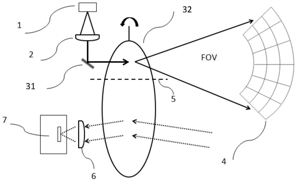
[0042] From figure 2 It can be seen that the laser radar optical system for transmitting and receiving synchronously in this embodiment includes a laser radar transmitting system and a laser radar receiving system. The laser radar transmitting system includes a pulse laser 1, a collimator lens group 2, a single-axis scanning galvanometer 31 and a single-axis scanning galvanometer 32 arranged in sequence along the optical path; the laser radar receiving system includes a single-axis scanning galvanometer arranged in sequence along the optical path 32 (the single-axis scanning vibrating mirror 32 and the single-axis scanning vibrating mirror 32 in the lidar transmitting system are the same single-axis scanning vibrating mirror), the receiving lens group 6 and the photodetector 7 . The single-axis scanning galvanometer can be a single-axis MEMS galvanometer or a one-dimensional rotating motor. The collimating lens group 2 in this embodiment includes at least one aspherical surf...

Embodiment 3

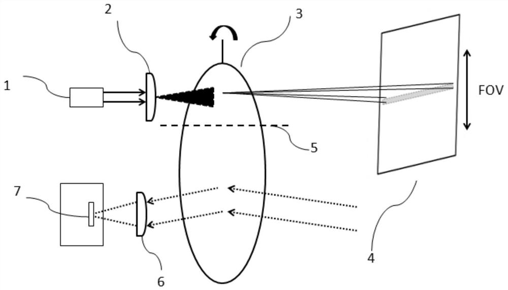
[0047] From image 3 It can be seen that the laser radar optical system for transmitting and receiving synchronously in this embodiment includes a laser radar transmitting system and a laser radar receiving system. Among them, the laser radar transmitting system includes a pulse laser 1, a collimating line expansion lens group 2 and a single-axis scanning galvanometer 3 arranged in sequence along the optical path; the laser radar receiving system includes a single-axis scanning galvanometer 3 arranged in sequence along the optical path, and a receiving lens group 6 and photodetector 7; wherein, the single-axis scanning vibrating mirror can be a single-axis MEMS vibrating mirror or a single-axis rotating motor.

[0048] The optical system of this embodiment also includes an isolation device 5, which is made of an opaque material and arranged perpendicular to the mirror surface of the uniaxial scanning vibrating mirror 3, and the uniaxial scanning vibrating mirror 3 is divided i...


PUM


Abstract

The invention belongs to the field of laser radar optical design system, and relates to a synchronous laser radar optical system for transmitting and receiving, which solves the problem that the synchronous rotation of two sets of vibrating mirrors cannot be accurately guaranteed and the coaxial optical system for transmitting and receiving is easy to reflect emitted stray light into a photoelectric detector. inaccurate test results. The optical system mainly includes a laser radar transmitting system and a laser radar receiving system; the scanning transmitting galvanometer in the laser radar transmitting system and the scanning receiving galvanometer in the laser radar receiving system are the same scanning galvanometer, and its surface is provided with The isolation device divides the scanning galvanometer into upper and lower parts, which are respectively used as a scanning transmitting galvanometer and a scanning receiving galvanometer. Realize the mutual non-interference of the transceiver optical system, eliminate the interference of stray light generated by the mixing of coaxial transceiver optical circuits on the received signal, and ensure that the frequency, amplitude and phase of the laser scanning system transmitting module and receiving module are completely consistent, greatly improving the test results reliability.

Description

technical field [0001] The invention belongs to the field of laser radar optical design systems, and relates to a transceiver synchronous laser radar optical system. Background technique [0002] LiDAR technology is the core technology of autonomous driving to make flexible responses and coping decisions like the human brain through the detection and understanding of the surrounding environment. A laser radar system with high stability, simple structure and high resolution is the goal that people have always wanted to achieve. [0003] The laser radar system includes scanning laser radar, which is mainly divided into traditional mechanical rotary scanning, all-solid-state scanning and MEMS (micro-electromechanical system) hybrid solid-state scanning. The rotary scanning laser radar is flexible in operation. It can realize the area array field of view detection by using a single point of laser light source, and realize its ranging function by calculating the time difference ...

Claims


Application Information

Patent Timeline
Patent Type & Authority Patents(China)
IPC IPC(8): G01S17/02G01S17/10G01S17/89G01S7/481
CPCG01S7/4817G01S17/02G01S17/08G01S17/89
Inventor 范乔丹夏长锋乔大勇徐法虎何耀军
Owner XI AN ZHISENSOR TECH CO LTD
Why Eureka
Try Eureka