Terminal

A terminal and transmitter technology, applied in the electronic field, can solve the problem of large noise floor of infrared sensors, and achieve the effect of reducing the noise floor

Active Publication Date: 2019-10-15
VIVO MOBILE COMM CO LTD
View PDF8 Cites 4 Cited by
  • Summary
  • Abstract
  • Description
  • Claims
  • Application Information

AI Technical Summary

Problems solved by technology

[0004] Embodiments of the present invention provide a terminal to solve the problem of large noise floor of infrared sensors in the prior art

Method used


Image

  • Terminal
  • Terminal
  • Terminal

Examples


Embodiment Construction

[0016] The following will clearly and completely describe the technical solutions in the embodiments of the present invention with reference to the accompanying drawings in the embodiments of the present invention. Obviously, the described embodiments are some of the embodiments of the present invention, but not all of them. Based on the embodiments of the present invention, all other embodiments obtained by persons of ordinary skill in the art without creative efforts fall within the protection scope of the present invention.

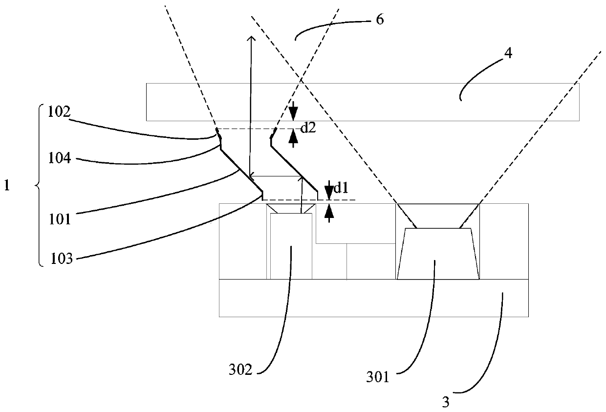
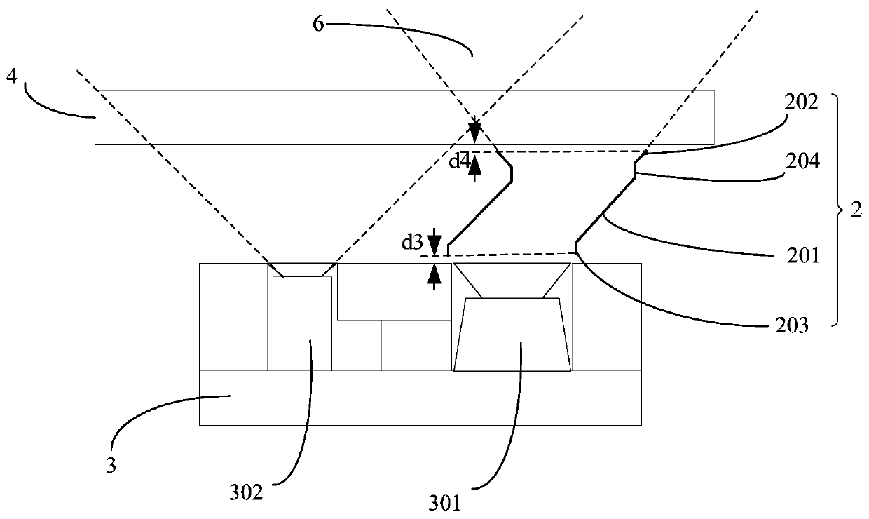
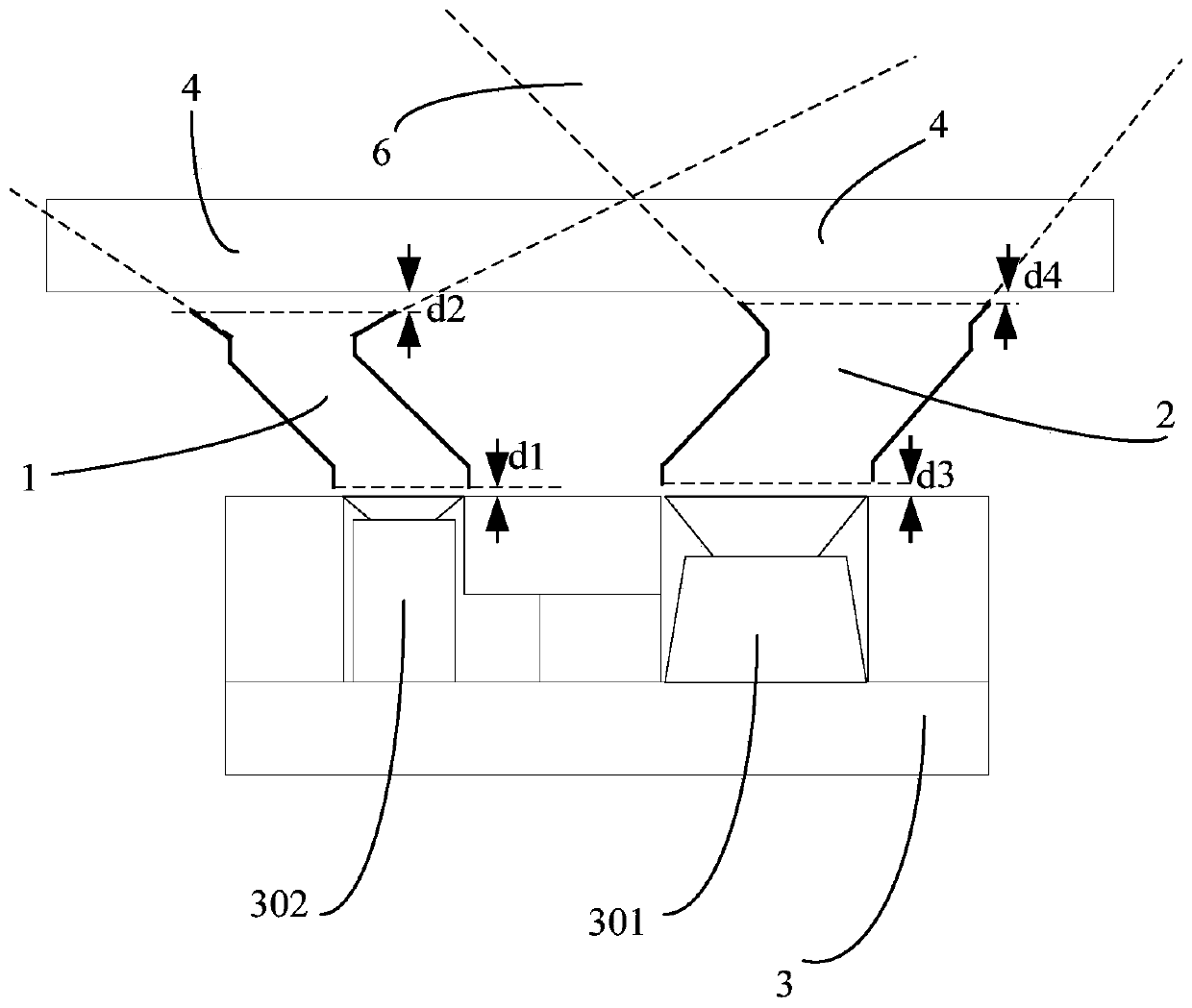
[0017] Embodiments of the present invention provide a terminal, such as Figures 1 to 3 As shown, the terminal includes:

[0018] Glass cover 4;

[0019] An infrared sensor 3, the infrared sensor 3 includes a transmitting end 302 and a receiving end 301;

[0020] The first light guide structure 1 and / or the second light guide structure 2, the first light guide structure 1 is fixed between the emitting end 302 and the glass cover plate 4, and the seco...


PUM


Abstract

The invention provides a terminal. The terminal comprises a glass cover plate; an infrared sensor including an emitting end and a receiving; a first light-guiding structure and/or a second light-guiding structure, wherein the first light-guiding structure is fixed between the emitting end and the glass cover plate, and the second light-guiding structure is fixed between the receiving end and the glass cover plate; the first light-guiding structure extends to the glass cover plate from a light-exiting surface of the emitting end in an inclined manner, and an inclination direction is far away from of positive projection of the receiving end on the glass cover plate; and the second light guiding structure extends to the glass cover plate from the light-exiting surface of the receiving end inthe inclined manner, and the inclination direction is far away from the positive projection of the emitting end on the glass cover plate. Therefore, the ground noise of the infrared sensor can be reduced.

Description

technical field [0001] The present invention relates to the field of electronic technology, in particular to a terminal. Background technique [0002] Most terminals use infrared sensors to achieve proximity detection. Infrared sensing consists of two parts: transmitting and receiving. When the distance of the measured object is different, the reflected infrared light energy is different, so distance detection can be realized. Among them, limited by space and cost, the infrared emission and reception are packaged in one device. The infrared sensor device is laid out on the PCB main board, and the infrared rays penetrate through the hidden hole on the glass cover, reflected by the blocking object, and return to the receiving end of the infrared device. Among them, when there is no shield above the terminal, part of the infrared light is reflected back to the receiving end by the surface of the glass cover, and the obtained infrared value is called the infrared "noise floor"...

Claims


Application Information

Patent Timeline
Patent Type & Authority Applications(China)
IPC IPC(8): G01S17/08G01S7/481
CPCG01S17/08G01S7/481G01S7/4813H04M1/026G01S17/04G01S7/4816G01S7/4814
Inventor 赵恒伟肖学军
Owner VIVO MOBILE COMM CO LTD
Why Eureka
Try Eureka