
Cyclone separation device

A technology of a cyclone separation device and a mounting body, which is applied in suction filters, cleaning equipment, vacuum cleaners, etc., can solve problems such as affecting the gas-solid separation efficiency of the cyclone separation device, easily blocking the filter screen cover, and large filter pressure of the filter element.

Pending Publication Date: 2019-10-18
SUZHOU CHENGHE CLEANING EQUIP
View PDF9 Cites 0 Cited by
  • Summary
  • Abstract
  • Description
  • Claims
  • Application Information

AI Technical Summary

Problems solved by technology

The above-mentioned dust directly escaping from the filter hole is not only easy to block the filter screen cover due to the entrained dust particles, but also brings a lot of filtration pressure to the downstream filter element, thus affecting the entire cyclone separation device. gas-solid separation efficiency

Method used


Image

  • Cyclone separation device
  • Cyclone separation device
  • Cyclone separation device

Examples


Embodiment Construction

[0033] In order to describe the technical content, structural features, achieved goals and effects of the invention in detail, the following will be described in detail in conjunction with the embodiments and accompanying drawings.

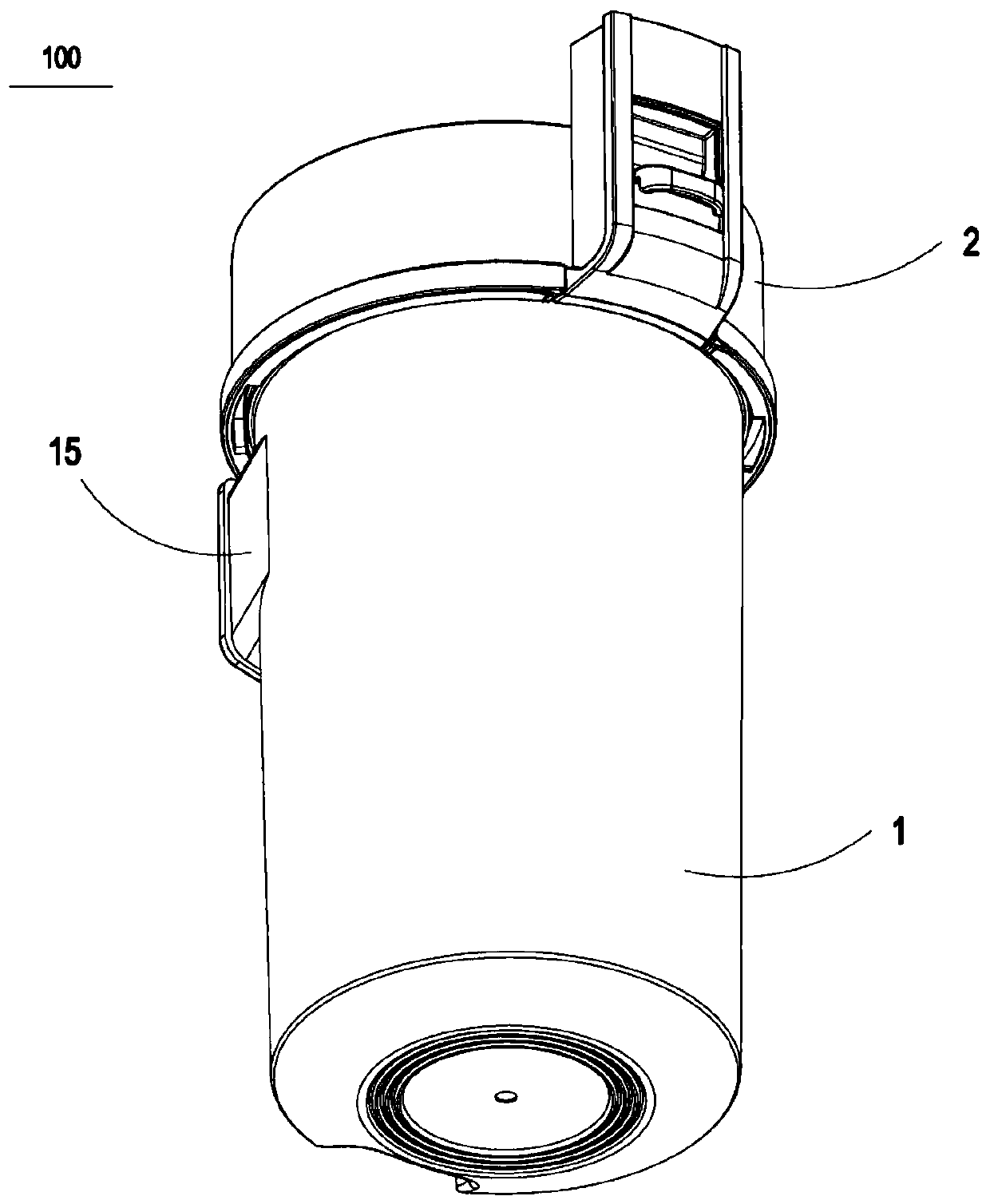
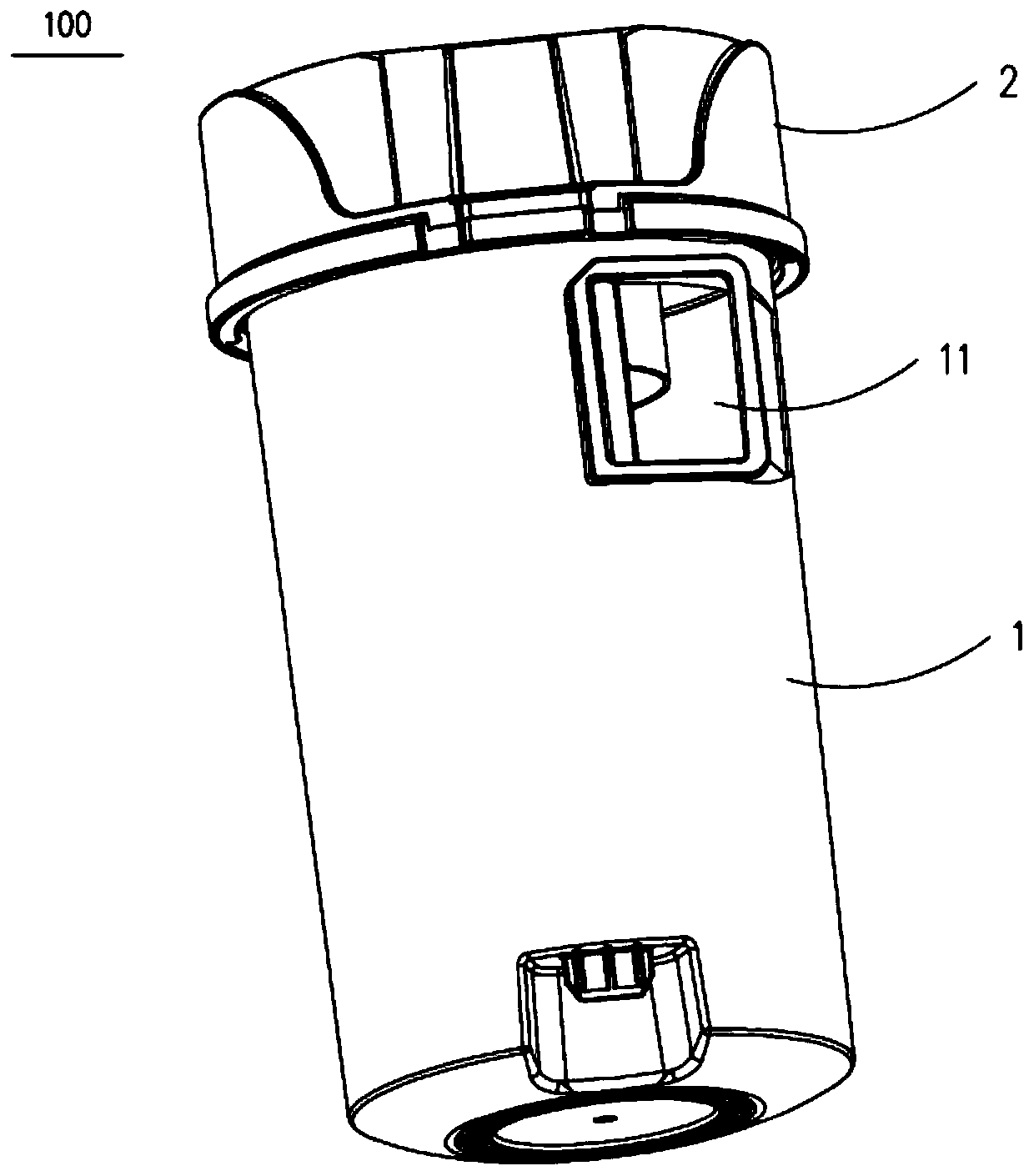
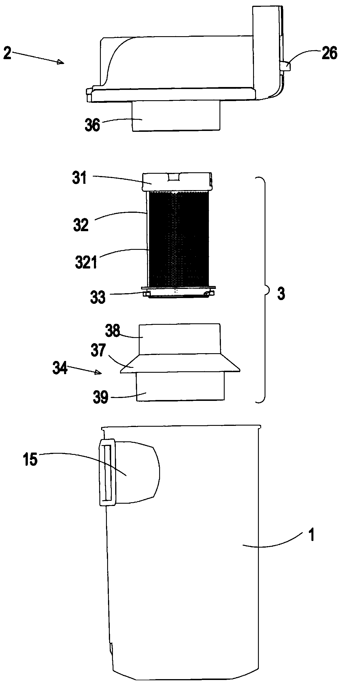
[0034] like Figure 1-3 As shown, the cyclone separation device 100 according to the embodiment of the present invention includes: a dust cup 1 , a top cover assembly 2 and a filter element assembly 3 . The filter element assembly 3 includes an upper mounting body 31 , a metal filter screen cover 32 with several filtering holes 321 , a lower mounting body 33 and a lower base 34 . The dust cup 1 is a structure with a closed bottom and an open top. The outside of the dust cup 1 is provided with a spiral air inlet 15 connected to the inside of the dust cup 1 , and the side wall of the dust cup 1 is provided with an air inlet 11 connected to the spiral air passage 15 . Due to the existence of the spiral air duct 15, the dust-laden airflow entering t...


PUM


Abstract

The invention discloses a cyclone separation device. The cyclone separation device comprises a dust cup with an air inlet formed in a side wall surface, a filter element assembly which is positioned in the dust cup and comprises a filter screen cover provided with a plurality of filter holes and a filter element outlet positioned in the upper part, and a check ring arranged inside the dust cup andshielded at the periphery of the upper part of the filter screen cover, wherein the air inlet, the filter holes and the filter element outlet communicate sequentially; the air inlet is configured tospirally guide dust-containing air flow entering the dust cup through the air inlet to the filter holes; the check ring is used for separating at least part of the air inlet from the filter holes in the upper part of the filter screen cover; and an air flow channel for guiding the dust-containing air flow to the filter holes in the upper part of the filter screen cover in a direction from bottom to top is formed between the check ring and the upper part of the filter screen cover. According to the cyclone separation device, equipment of the check ring can prevent dust from being suspended on the periphery of the upper part of the filter screen cover or blocking the filter holes in the upper part of the filter screen cover to influence the air-ash separation effect.

Description

technical field [0001] The invention relates to the field of vacuum cleaning equipment, in particular to a cyclone separation device for gas-solid separation. Background technique [0002] In the cyclone separation device of the existing vacuum cleaner, the dust-laden airflow enters the cyclone separation chamber from the side air inlet of the dust cup for gas-solid separation. After the gas-solid separation in the cyclone separation chamber, large particles of dust will stay in the dust cup , the small particles of dust along with the air flow pass through the filter screen inside the cyclone separation chamber and then discharge to the outside of the dust cup. discharged to the outside world. In the prior art, since the air inlet of the dust-laden airflow is close to the upper part of the filter screen cover, a part of the dust-laden airflow entering from the air inlet always passes directly through the filter holes on the upper part of the filter screen cover and escapes...

Claims


Application Information

Patent Timeline
Patent Type & Authority Applications(China)
IPC IPC(8): A47L9/16
CPCA47L9/16A47L9/1608A47L9/1683
Inventor 卞庄
Owner SUZHOU CHENGHE CLEANING EQUIP
Learn More