Melting treatment system for waste incineration fly ash

A waste incineration fly ash and processing system technology, which is applied in the field of waste incineration fly ash fusion processing system, can solve the problems of secondary fly ash pollution, weakening of combustion intensity, and slagging at the slag mouth, so as to avoid secondary pollution and save energy. Water resources, the effect of preventing slagging and clogging

Pending Publication Date: 2021-11-02
WUHAN WUGUO ENERGY ENG CO LTD
View PDF2 Cites 0 Cited by
  • Summary
  • Abstract
  • Description
  • Claims
  • Application Information

AI Technical Summary

Problems solved by technology

[0004] The invention patent with publication number CN1632376A discloses a cyclone furnace high-temperature melting treatment method for waste incineration fly ash. The method uses pulverized coal as an auxiliary fuel to generate high temperature in the cyclone furnace to melt waste incineration fly ash; The flue gas outlet of the cyclone furnace mentioned above is located at the lower part of the combustion chamber, and the descending flue gas will carry a large amount of secondary fly ash into the rear system to cause secondary pollution
[0005] The invention patent with the publication number CN111112299A discloses a melting furnace for melting garbage fly ash and its supporting burner. The specially designed burner generates a swirling airflow in the furnace. The high-speed swirling airflow can strengthen combustion, but with the airflow When going down to the slag outlet, the combustion intensity will be weakened, and slagging will easily occur at the slag outlet, resulting in poor slag discharge. In addition, the device also has secondary fly ash pollution problems

Method used


Image

  • Melting treatment system for waste incineration fly ash
  • Melting treatment system for waste incineration fly ash
  • Melting treatment system for waste incineration fly ash

Examples


Embodiment Construction

[0029] In order to make the purpose, technical solution and advantages of the invention clearer, the invention will be further elaborated below in conjunction with the accompanying drawings.

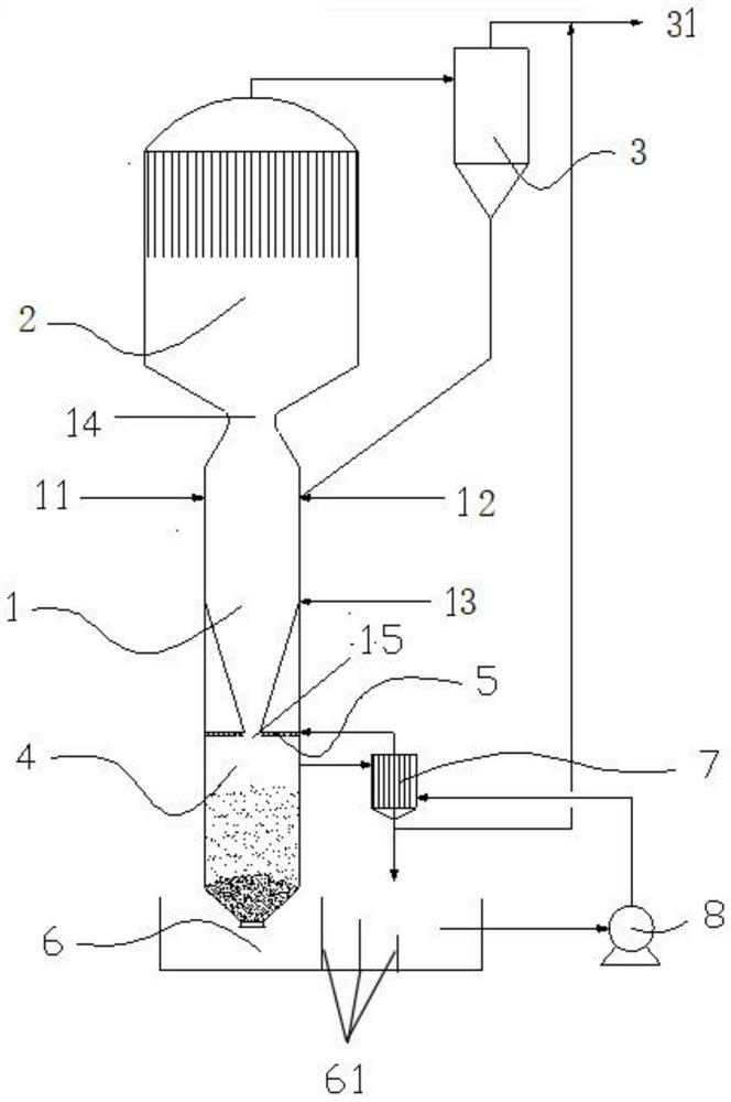
[0030] In this example, if figure 1 As shown, the waste incineration fly ash melting treatment system includes a circulating swirling combustion melting system and a slag quenching water circulation system.

[0031] The circulating swirling combustion melting system includes a combustion melting chamber 1, a flue gas cooling chamber 2, and an ash trapping chamber 3. The top of the ash trapping chamber 3 is provided with a gas outlet 31; the combustion melting chamber 1 is a swirling combustion melting chamber, and the combustion dust particles Outward swirling flow, flue gas forms internal swirling flow, the upper part of the combustion melting chamber 1 is a hollow cylinder, the upper part of the cylindrical cylinder is tangentially provided with a primary auxiliary fuel inlet 11, fly a...


PUM


Abstract

The invention discloses a melting treatment system for waste incineration fly ash. The melting treatment system comprises a circulating rotational flow combustion melting system and a slag chilling water circulation system; the circulating rotational flow combustion melting system comprises a combustion melting chamber, a flue gas cooling chamber and an ash catching chamber, and the ash catching chamber is provided with a gas outlet; a plurality of inlets are formed in the combustion melting chamber, and a smoke outlet is formed in the combustion melting chamber; the combustion melting chamber communicates with the flue gas cooling chamber, the flue gas cooling chamber communicates with the ash catching chamber, and the ash catching chamber communicates with the combustion melting chamber; the slag chilling water circulation system comprises a chilling chamber, a spraying ring, a slag water tank, a condensation chamber and a water pump; fly ash in the combustion melting chamber is combusted into liquid molten slag, the liquid molten slag enters the chilling chamber through a slag discharging opening in the bottom of the combustion melting chamber to form glassy slag, water vapor in the chilling chamber is liquefied into water through the condensation chamber and flows into the slag water tank, a valve at the bottom of the chilling chamber is opened, and the water and the glassy slag in the chilling chamber are discharged into the slag water tank; and water in the slag water tank circulates between the slag water tank and the chilling chamber through the water pump, and slag in the slag water tank can be used as a roadbed or a building material.

Description

technical field [0001] The invention relates to the technical field of environmental protection and hazardous waste treatment, in particular to a waste incineration fly ash fusion treatment system. Background technique [0002] Garbage incineration is an important development direction of garbage harmless treatment in my country in recent years. Garbage incineration is not the final disposal method of garbage. Bottom ash and fly ash will be produced during the incineration process. Fly ash is far more harmful than bottom slag. The treatment of it has also attracted the attention of scholars from all over the world. [0003] The fly ash melting solidification method has obvious technical advantages over other solidification disposal technologies, and is more suitable for the current national conditions. The fly ash is directly calcined at 1100-1500 °C, and the glassy component of the fly ash itself is heated and melted to form a silica The dense network structure composed of ...

Claims


Application Information

Patent Timeline
Patent Type & Authority Applications(China)
IPC IPC(8): F23G5/08F23G5/44F23G7/00F23J15/06F23J15/02F23J15/04
CPCF23G5/08F23G5/44F23G7/00F23J15/06F23J15/02F23J15/04
Inventor 王大伟邹涛史建波张亮
Owner WUHAN WUGUO ENERGY ENG CO LTD
Why Eureka
Try Eureka