A die-casting mold for a 5G signal booster
A signal booster and die-casting mold technology, applied in the field of die-casting molds, can solve problems such as the inability to guarantee that die-casting parts will not form bubbles, and achieve the effect of uniform solute
- Summary
- Abstract
- Description
- Claims
- Application Information
AI Technical Summary
Problems solved by technology
Method used
Image

Examples
specific Embodiment approach 1
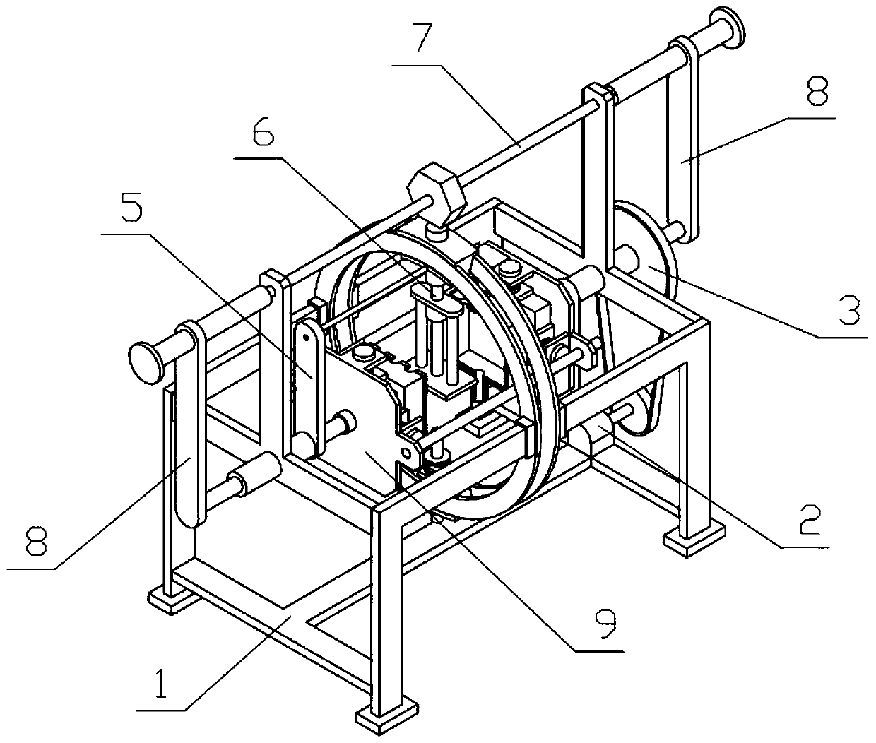
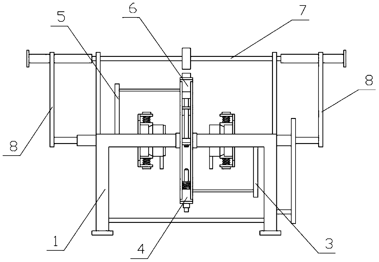
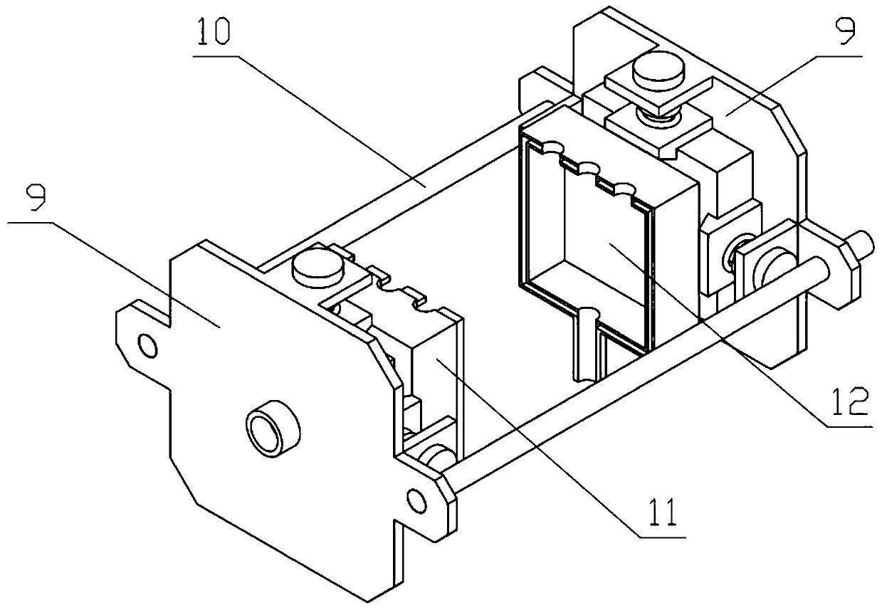
[0037] Combine below Figure 1-13 Describe this embodiment, a die-casting mold for a 5G signal booster, including a device bracket 1, a driving mechanism 2, a rotating mechanism I3, an injection molding mechanism 4, a rotating mechanism II5, a drainage mechanism 6, a clamping screw 7, and a clamping push rod 8. Clamping mechanism 9, positioning sliding column 10, injection mold Ⅰ11 and injection mold Ⅱ12, the drive mechanism 2 is fixedly connected to the device bracket 1, the rotation mechanism Ⅰ3 is rotatably connected to the device bracket 1, and the drive mechanism 2 and the rotation mechanism Ⅰ3 are driven connection, the injection mechanism 4 is slidingly connected to the device bracket 1, the injection mechanism 4 is fixedly connected to the eccentric position of the rotation mechanism I3, the rotation mechanism II5 is rotatably connected to the device bracket 1, the drainage mechanism 6 is slidingly connected to the device bracket 1, and the drainage mechanism 6. It is ...
specific Embodiment approach 2
[0039] Combine below Figure 1-13 Describe this embodiment, this embodiment will further explain the first embodiment, the device bracket 1 includes a support ring 1-1, a support foot 1-2, a support plate 1-3 and a motor support plate 1-4, the support ring 1- 1 is provided with two, both sides of the two support rings 1-1 are fixedly connected with support legs 1-2, and the outer sides of the two support legs 1-2 on both sides are fixedly connected with support plates 1-3, The motor supporting board 1-4 is fixedly connected between the four supporting feet 1-2, and the driving mechanism 2 is fixedly connected on the motor supporting board 1-4.
specific Embodiment approach 3
[0041] Combine below Figure 1-13 Describe this embodiment. This embodiment will further explain Embodiment 2. The rotating mechanism I3 includes a rotating cylinder I3-1 and a rotating connecting rod I3-2. The rotating cylinder I3-1 is rotatably connected to a support plate 1-3 on one side. Above, the rotating cylinder I3-1 is fixedly connected with the rotating connecting rod I3-2, and the rotating connecting rod I3-2 is connected with the driving mechanism 2 through a belt transmission.
PUM
 Abstract
Description
Claims
Application Information