
Injection mold for buffering L-shaped sheets

An injection mold, L-shaped technology, applied in the field of injection molds for buffering L-shaped pieces, can solve problems such as product surface depression, and achieve the effect of ensuring product dimensional accuracy

Active Publication Date: 2019-10-18
友信精密实业(深圳)有限公司
View PDF9 Cites 2 Cited by
  • Summary
  • Abstract
  • Description
  • Claims
  • Application Information

AI Technical Summary

Problems solved by technology

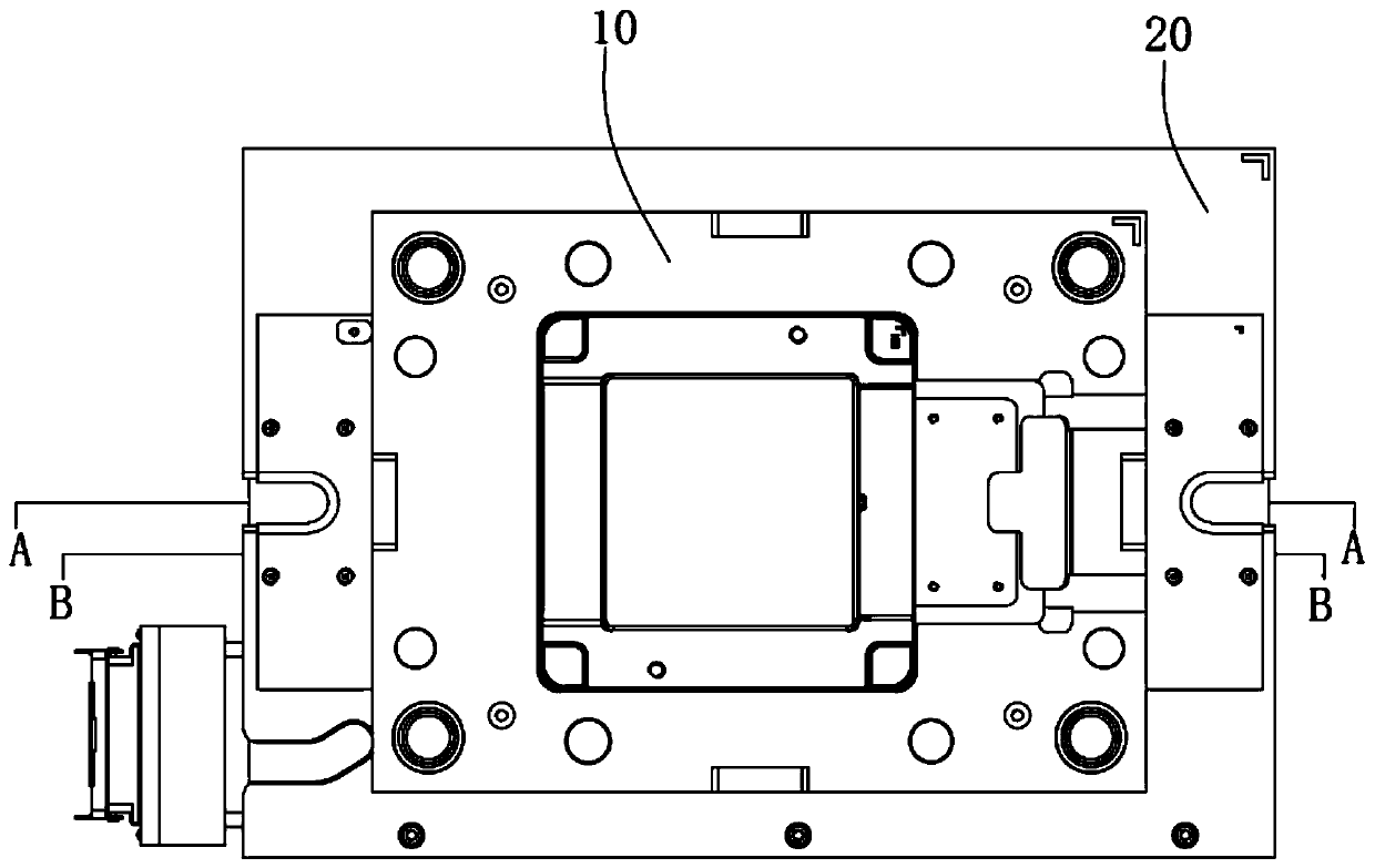
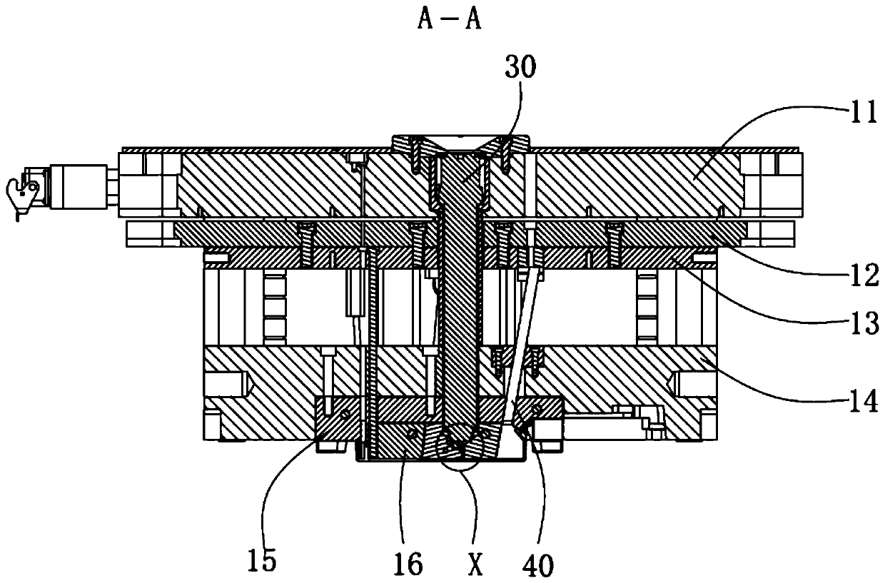
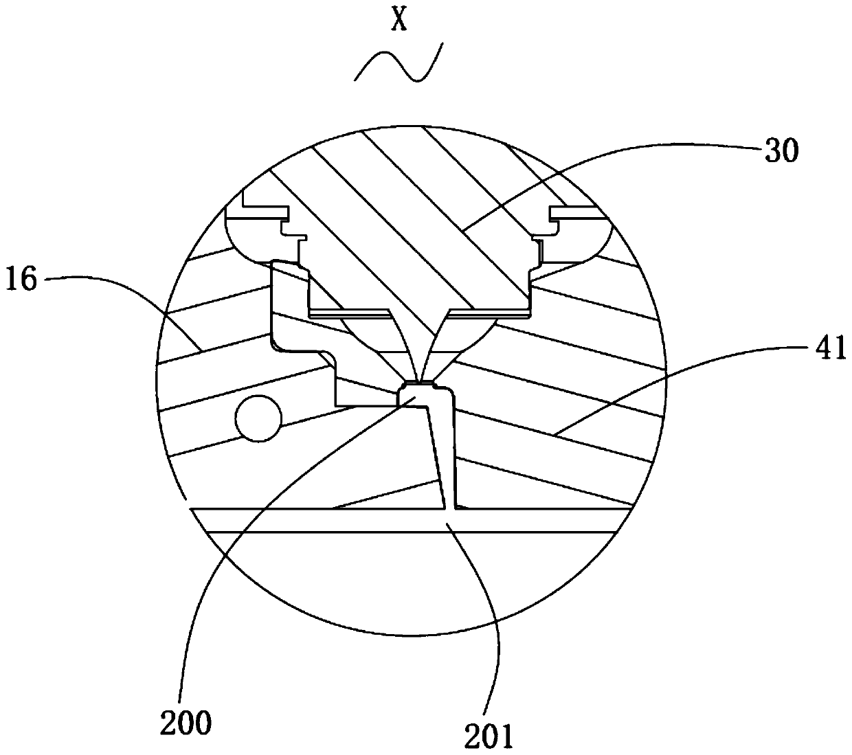
[0007] The purpose of the present invention is to provide an injection mold for cushioning L-shaped pieces, so as to solve the problem that the existing injection molds easily cause depressions on the product surface

Method used


Image

  • Injection mold for buffering L-shaped sheets
  • Injection mold for buffering L-shaped sheets
  • Injection mold for buffering L-shaped sheets

Examples


Embodiment Construction

[0030] In order to facilitate the understanding of the present invention, the present invention will be described more fully below with reference to the associated drawings. Several embodiments of the invention are shown in the drawings. However, the present invention can be embodied in many different forms and is not limited to the embodiments described herein. Rather, these embodiments are provided so that the disclosure of the present invention will be thorough and complete.

[0031] It should be noted that when an element is referred to as being “fixed on” another element, it may be directly on the other element or there may be an intervening element. When an element is referred to as being "connected to" another element, it can be directly connected to the other element or intervening elements may also be present. The terms "vertical," "horizontal," "left," "right," and similar expressions are used herein for purposes of illustration only.

[0032] Unless otherwise def...


PUM


Abstract

The invention belongs to the technical field of injection molding, and provides an injection mold for buffering L-shaped sheets. The injection mold comprises a front mold structure and a rear mold structure, wherein the front mold structure comprises an upper mold plate, a feeding assembly, an ejector pin bottom plate, an ejector pin panel, an upper mold block, an upper mold core, an insert and aninclined top assembly; and the inclined top assembly comprises an inclined top head, an inclined top rod, an inclined top pin, an inclined top base, a pin and a fixing assembly, wherein the upper endof the inclined top base is connected to the ejector pin panel, the insert and the inclined top head form an L-shaped cavity, and the L-shaped cavity is in communication with a product cavity. Duringmachining, the feeding assembly is used for feeding glue, the L-shaped cavity is impacted firstly, so that the glue flow does not directly impact the product cavity, and the buffering effect can be realized; when the glue material flows into the product cavity, the sectional area of the L-shaped cavity is larger than that of a glue inlet of the feeding assembly, the flow rate is reduced, and theproblems that the appearance of the front surface of the product is free of bubbles, trapped gas, jet lines and shrinkage cavities are solved; and the L-shaped cavity is arranged in the middle of theproduct cavity, the distance from the glue inlet to the periphery of the product is shorter, and the product size precision is ensured.

Description

technical field [0001] The invention relates to the technical field of injection molding, in particular to an injection mold for cushioning L-shaped pieces. Background technique [0002] In the shell products of injection molding, there is a type of shell whose surface is a smooth plane, and there are many connecting ribs and positioning plates inside. Therefore, when injection molding, the product is required to have a good front appearance and no basic defects. . The difficulty is the choice of the location and style of the glue inlet. When a gate close to the side of the product is used, the distance from filling to the opposite side will be longer, and the injection pressure will be high, resulting in differences in the side length of the product. When several gates are used to fill simultaneously from positions close to the side, the rubber material will outflank the product from the side to the middle of the product, and defects such as weld lines and trapped air wil...

Claims


Application Information

Patent Timeline
IPC IPC(8): B29C45/26B29C45/40
CPCB29C45/26B29C45/2602B29C45/4005
Inventor 章庆华
Owner 友信精密实业(深圳)有限公司
Learn More