
Structure of connection joint between local laminated slab and composite wall column

A technology for connecting nodes and laminated boards, which is applied in building structures, buildings, etc., can solve the problems of low processing efficiency of prefabricated components, increase the difficulty of transportation and protection of finished products, etc. The effect of the operation steps

Active Publication Date: 2019-10-18
ZHEJIANG DADONGWU CONSTR TECH CO LTD
View PDF6 Cites 1 Cited by
  • Summary
  • Abstract
  • Description
  • Claims
  • Application Information

AI Technical Summary

Problems solved by technology

Reserving the overhanging steel bars in this way leads to low processing efficiency of prefabricated components, and also increases the difficulty of transportation and product protection

Method used


Image

  • Structure of connection joint between local laminated slab and composite wall column
  • Structure of connection joint between local laminated slab and composite wall column
  • Structure of connection joint between local laminated slab and composite wall column

Examples


Embodiment Construction

[0020] The present invention will be further described below in conjunction with the embodiments in the accompanying drawings.

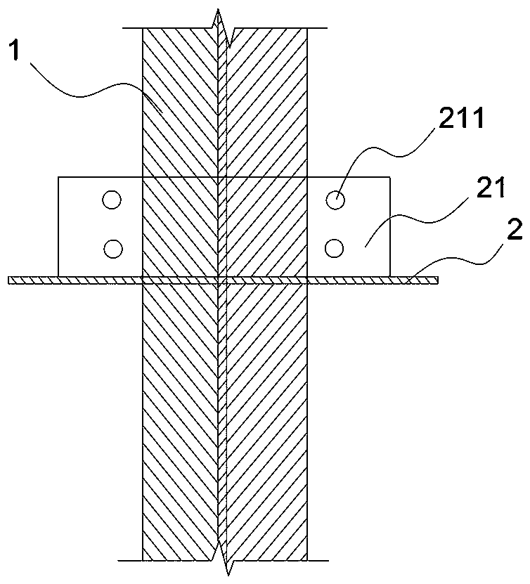
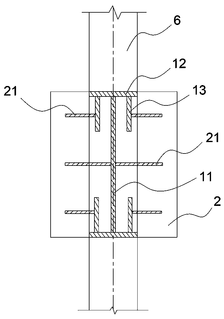
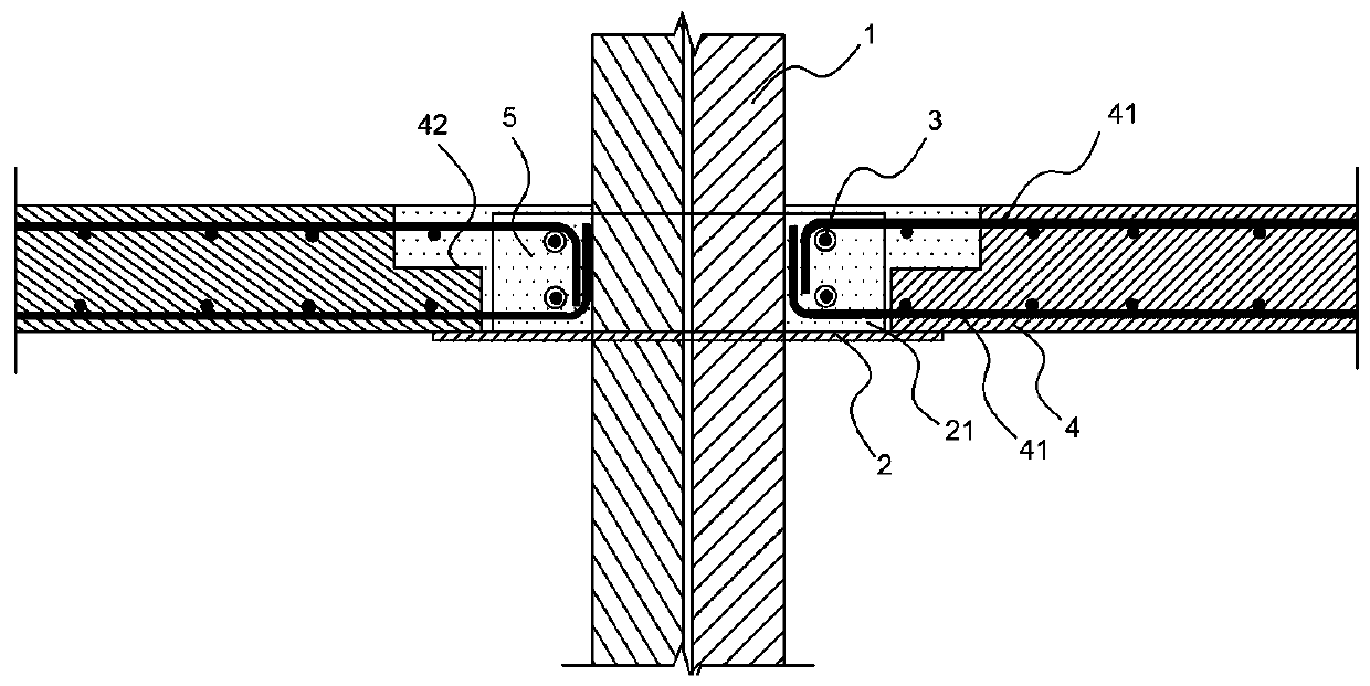
[0021] Such as Figure 1 to Figure 3 The connection node structure between a partially laminated plate and a combined wall column shown includes a combined wall column 1 and a partially laminated plate 4 , and beams 6 are provided on both sides of the combined wall column 1 . The combined wall column 1 is provided with a supporting plate 2 , the supporting plate 2 is provided with a rib 21 , the rib 21 is provided with an opening 211 , and the opening 211 is provided with a rib 3 . The ends of the partial laminated board 4 are erected on the supporting plate 2, and the reinforcing bars 41 on the local laminated board 4 pass through the upper or lower ends of the pierced ribs 3, and bend toward the pierced ribs 3 and the middle part of the combined wall column 1. The joint structure uses the "pin shaft" effect of the rib plate 21 and the penetrating ...


PUM


Abstract

The invention provides a structure of a connection joint between a local laminated slab and a composite wall column. The structure includes the composite wall column and the local laminated slab. A supporting plate is arranged on the composite wall column. A ribbed slab is arranged on the supporting plate. The ribbed slab is provided with holes. The end of the local laminated slab is arranged on the supporting plate. Through ribs are arranged in the holes. Steel bars on the local laminated slab extend from the side of the through ribs to between the through ribs and the composite wall column.The structure of the joint can cancel the reservation of extension steel bars and facilitates the processing and transportation.

Description

technical field [0001] The invention relates to the technical field of construction, in particular to a connection node structure between a partially laminated plate and a combined wall column. Background technique [0002] Partially laminated slabs and partially filled composite walls and columns are new parts in the field of prefabricated construction engineering, and there are no relevant design specifications, standards or atlases for their connection nodes. In some research materials, the above-mentioned connection nodes are that the floor reinforcement passes through partially filled composite walls and columns, or the floor reinforcement is welded to partially filled composite walls and column steel plates. The length of the reserved overhanging steel bars for these two schemes must meet the requirements of relevant specifications: the length of the overhanging surface layer steel bars should not be less than 1 / 4 of the slab span, and for slabs with a span of 3m, the ...

Claims


Application Information

Patent Timeline
Patent Type & Authority Applications(China)
IPC IPC(8): E04B1/38
CPCE04B1/38
Inventor 覃祚威周鹏洋任洋洋李慧
Owner ZHEJIANG DADONGWU CONSTR TECH CO LTD
Learn More