
Redundant joint attachment method and system

A joint attachment and redundancy technology, applied in the field of communication, can solve the problem that MSC calls cannot be established, and achieve the effect of improving business connection ability and success rate

Active Publication Date: 2019-10-18
CHINA UNITED NETWORK COMM GRP CO LTD
View PDF4 Cites 5 Cited by
  • Summary
  • Abstract
  • Description
  • Claims
  • Application Information

AI Technical Summary

Problems solved by technology

[0004] In order to at least partly solve the technical problem that the call cannot be established when the joint attached MSC fails or the SGs interface between the MSC and the MME fails in the prior art, the present invention is completed

Method used


Image

  • Redundant joint attachment method and system
  • Redundant joint attachment method and system

Examples


Embodiment 1

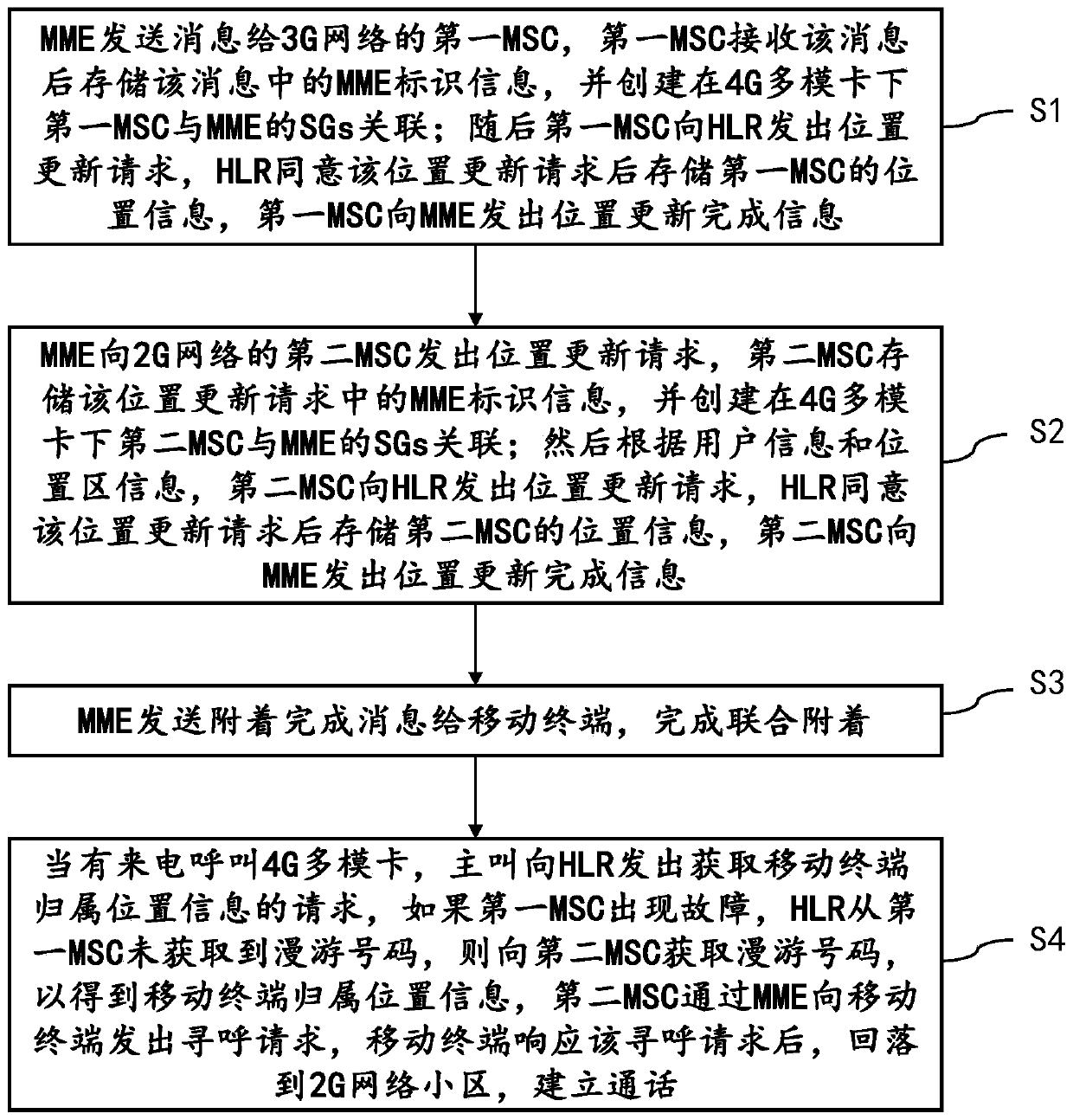
[0032] Such as figure 1 As shown, the present invention provides a method for redundant joint attachment, including:

[0033] Step S1: The MME sends a message to the first MSC of the 3G network, and the first MSC stores the MME identification information in the message after receiving the message, and creates an association between the first MSC and the MME's SGs under the 4G multimode card; then the first MSC The MSC sends a location update request to the HLR, and the HLR agrees to the location update request and stores the location information of the first MSC, and the first MSC sends a location update completion message to the MME;

[0034] Step S2: The MME sends a location update request to the second MSC of the 2G network, and the second MSC stores the MME identification information in the location update request, and creates an association between the second MSC and the MME's SGs under the 4G multimode card; then according to the user information and location area infor...

Embodiment 2

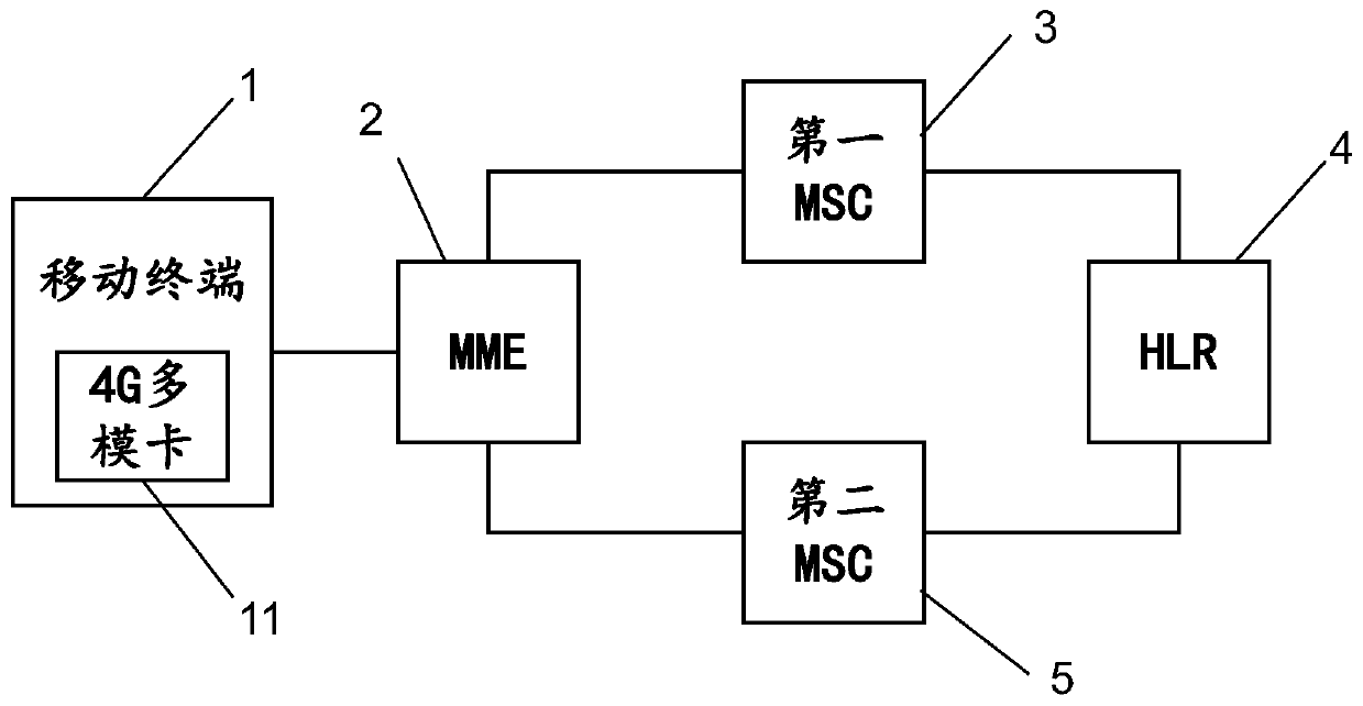
[0048] According to another aspect of the present invention, such as figure 2 As shown, the present invention also provides a redundant joint attachment system, including: mobile terminal 1, MME2, first MSC3, HLR4, and second MSC5; the first MSC corresponds to the 3G network, and the second MSC corresponds to 2G network; the mobile terminal 1 includes a 4G multimode card 11;

[0049] The MME2 is used to send a message to the first MSC3 of the 3G network, and the first MSC3 is used to store the MME2 identification information in the message after receiving the message, and create SGs between the first MSC3 and the MME2 under the 4G multimode card 11 Association; and sending a location update request to HLR4, the HLR4 is used to store the location information of the first MSC3 after agreeing to the location update request; the first MSC3 is also used to send location update completion information to the MME2;

[0050] The MME2 is also used to send a location update request to ...


PUM


Abstract

The invention provides a redundant joint attachment method, which comprises the following steps: an MME (Mobility Management Entity) sends a message to a VLR (Virtual Local Area Network) correspondingto a 3G (The 3rd Generation Telecommunication) network, and the VLR stores MME information and creates SGs (Serving Gateway) association between an MSC (Mobile Switching Center) of the 3G network andthe MME; the HLR stores the MSC position information of the 3G network; then the MME sends a position updating request to the MSC of the 2G network, and the VLR of the 2G network stores MME information and creates a related SGs association; the HLR stores the position information of the 2G network MSC; and when there is an incoming call, if the MSC of the 3G network fails, the HLR acquires a roaming number from the MSC of the 2G network to obtain the home location information of the mobile terminal, and the mobile terminal falls back to the 2G network cell to establish a call. The invention further comprises a corresponding system. According to the redundant joint attachment method and system, when the 4G multimode card has voice service and needs to fall back and the MSC of the 3G network is abnormal or the corresponding SGs interface fails, the call request is completed by the attached MSC of the 2G network, so that the service connection capability and the success rate are improved.

Description

technical field [0001] The present invention relates to the field of communication technology, in particular to a redundant joint attachment method and a redundant joint attachment system. Background technique [0002] CSFB (Circuit Switched Fallback, Circuit Switched Fallback) is a communication technology that provides voice services based on a circuit domain network. In the initial stage of LTE (Long Term Evolution, long-term evolution) network deployment, CSFB is used as the voice service implementation technology in the initial stage of LTE network deployment. When the terminal performs voice services, the control terminal falls back to 3G (3rd-Generation, third-generation mobile communication technology ) or 2G (Second Generation, second-generation mobile communication technology) network, using the high coverage and mature technology of the 3G / 2G network to provide users with a good user experience. [0003] A typical CSFB service process mainly includes joint attach...

Claims


Application Information

Patent Timeline
Patent Type & Authority Applications(China)
IPC IPC(8): H04W36/00H04W36/32H04W88/06
CPCH04W36/0011H04W36/0079H04W36/32H04W88/06
Inventor 张余
Owner CHINA UNITED NETWORK COMM GRP CO LTD
Learn More