
Mounting method of wall type energy dissipation device

An installation method and energy dissipator technology, which are used in protective buildings/shelters, building components, earthquake-proof and other directions, can solve the problem of high cost of wall-type energy dissipator connectors, difficult to install accurately, quickly, and unclear force transmission. and other problems, to achieve the effect of easy maintenance and replacement, convenient and precise installation accuracy, and clear force transmission

Active Publication Date: 2017-03-22
KUNMING UNIV OF SCI & TECH
View PDF5 Cites 0 Cited by
  • Summary
  • Abstract
  • Description
  • Claims
  • Application Information

AI Technical Summary

Problems solved by technology

[0004] The technical problem to be solved by the present invention is to provide an installation method of a wall-type energy dissipator, which is used to solve the problems of high cost of wall-type energy dissipator connectors, unclear force transmission, and difficult to install accurately and quickly. To improve the installation efficiency and installation quality of the wall-type energy dissipator, ensure the normal energy dissipation capacity during an earthquake, and facilitate maintenance and replacement after the earthquake

Method used


Image

  • Mounting method of wall type energy dissipation device
  • Mounting method of wall type energy dissipation device
  • Mounting method of wall type energy dissipation device

Examples


Embodiment 1

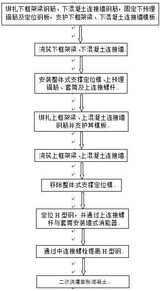
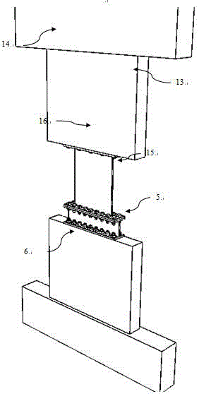
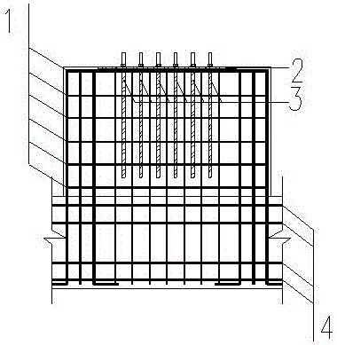
[0032] Embodiment 1: as Figure 1-12 As shown, the connection mode of the wall-type energy dissipator of the present invention adopts the cast-in-place concrete connection wall as the connection member of the energy dissipator, and its installation method is generally realized in this way: firstly, the lower frame beam 4 and the lower concrete connection wall steel bar 1 are bound, Then fix the pre-embedded anchor bar 3 and the positioning steel plate 2, then support the formwork of the lower frame beam 6 and the lower concrete connecting wall 5, then pour the lower frame beam 6 and the lower concrete connecting wall 5, and then install the adjustable support positioning formwork 9 (that is, the integral support positioning formwork), the upper pre-embedded anchor bar 7, the inner threaded sleeve 8 and the upper connecting screw 12, then bind the upper frame beam 14, the formwork of the upper concrete connecting wall 13 and support the steel cage, and then pour The upper frame...


PUM

PropertyMeasurementUnit
Thicknessaaaaaaaaaa

Abstract

The invention relates to a mounting method of wall type energy dissipation device, and belongs to the technology and construction field of construction engineering energy dissipation and shock absorption. The method comprises the step of firstly binding lower frame beam rebars and lower concrete connecting wall rebars, then fixing lower pre-buried anchor bars and a locating steel plate, afterwards shoring the frameworks of a lower frame beam and a lower concrete connecting wall, then conducting pouring on the lower frame beam and the lower concrete connecting wall, whereafter mounting adjustable supporting and locating models, upper pre-buried anchor bars, sleeves and upper connecting threaded rods, then binding upper frame beam rebars, upper concrete connecting wall rebars and shoring the frameworks thereof, afterwards conducting pouring on upper frame beam and upper concrete connecting wall, then removing the integral supporting and locating models, then locating H-shaped steel, then connecting the top of the wall type energy dissipation device to the upper connecting wall through the upper threaded rods and the sleeves, uplifting the H-shaped steel by the adjusting effect of middle connecting bolts, finally conducting secondary pouring on microexpanded concrete, and accordingly finishing the mounting of the wall type energy dissipation device. The mounting method of wall type energy dissipation device has the advantages of being convenient to build and simple and fast in detection and replacing after shock.

Description

technical field [0001] The invention relates to a method for installing a wall-type energy dissipator, which belongs to the construction field of energy dissipation and shock absorption technology in construction engineering. Background technique [0002] Earthquake is a very serious natural disaster. During the earthquake, the surface buildings will be distorted and deformed. When the earthquake is relatively strong, they will even collapse, causing huge economic losses and casualties. In order to reduce earthquake disasters in buildings, energy dissipation technology has received extensive attention. [0003] At present, there are many types of energy dissipation and shock absorption products. Wall dampers are favored by designers for their efficient energy dissipation capacity and friendly architectural style. The connection methods are also rich and varied, but most connection methods use steel components, which are expensive , the force transmission mechanism of some c...

Claims


Application Information

Patent Timeline
IPC IPC(8): E04B1/98E04H9/02
CPCE04H9/021
Inventor 张龙飞刘颖伸陶忠张丹
Owner KUNMING UNIV OF SCI & TECH
Learn More