
A non-contact real-time eccentricity detection method for a helical milling device

A helical milling hole, non-contact technology, applied in the direction of measuring/indicating equipment, metal processing equipment, metal processing machinery parts, etc., can solve the problem that the actual value of the eccentricity cannot be detected in real time

Active Publication Date: 2020-12-11
DALIAN UNIV OF TECH
View PDF8 Cites 0 Cited by
  • Summary
  • Abstract
  • Description
  • Claims
  • Application Information

AI Technical Summary

Problems solved by technology

[0005] The object of the present invention is to provide a non-contact real-time eccentricity detection method for a helical milling device during the eccentricity detection process of the helical milling hole, so as to solve the problem that the actual value of the eccentricity cannot be detected in real time in the prior art

Method used


Image

  • A non-contact real-time eccentricity detection method for a helical milling device
  • A non-contact real-time eccentricity detection method for a helical milling device
  • A non-contact real-time eccentricity detection method for a helical milling device

Examples


Embodiment 1

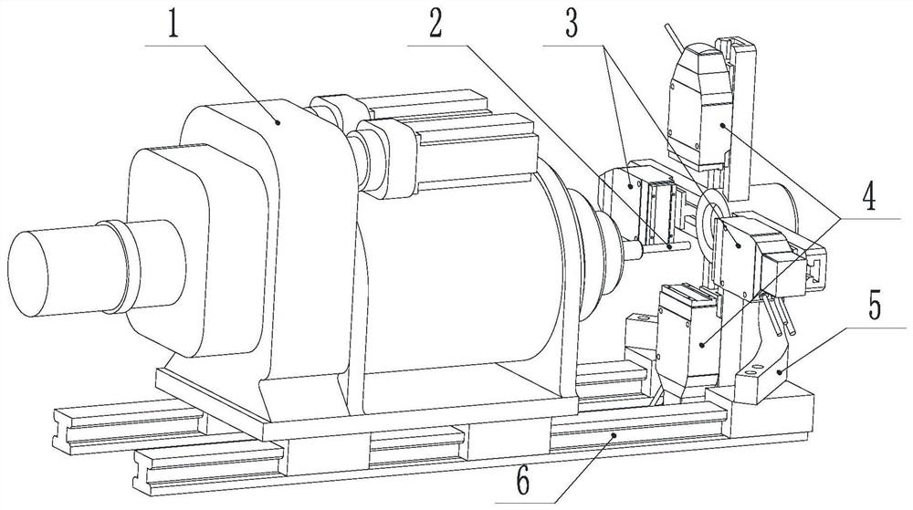
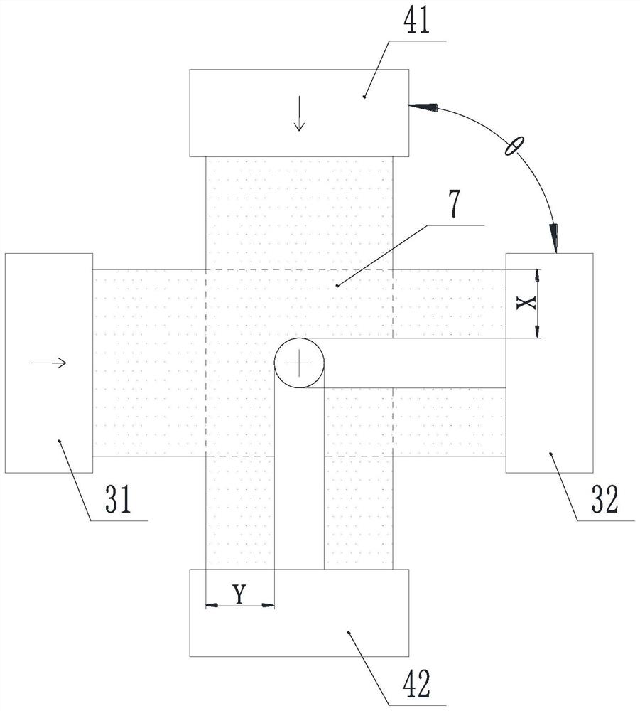
[0055] Such as figure 1 As shown, the laser detection device includes a first laser detection device 3 and a second laser detection device 4, and the first laser detection device 3 and the second laser detection device 4 are installed perpendicularly to each other in a plane perpendicular to the feeding direction of the tool 2. A laser detection device 3 includes a first laser detection device emitting pole 31 and a first laser detection device receiving pole 32 installed on the bracket 5 opposite to each other, and a second laser detection device 4 includes a second laser detection device installed on the bracket 5 opposite to each other. The emitter 41 of the detection device and the receiver 42 of the second laser detection device, the support 5 is installed on the base 6 of the automatic helical milling device 1, and the automatic helical milling device 1 can realize the self-rotation of the tool 2, the revolution of the tool 2, the axial Feed and automatic eccentric adjus...


PUM


Abstract

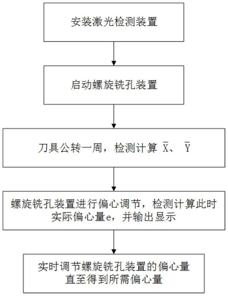
The invention discloses a non-contact real-time eccentric amount detection method for a spiral hole-milling device. The non-contact real-time eccentric amount detection method for the spiral hole-milling device comprises the following steps: installing a laser detection device to form a detection area; enabling a tool to penetrate through the detection area; while the tool revolves by one cycle, detecting the shortest distances from the tool to the upper edge and the left edge of the detection area every moment, denoting the shortest distances as an upper edge distance and a left edge distanceseparately, evaluating the average value of the upper edge distance and the average value of the left edge distance to adjust the eccentric amount of the spiral hole-milling device, detecting the shortest distances from the tool to the upper edge and the left edge of the detection area at a certain moment, denoting the shortest distances as a real-time upper edge distance Xn and a real-time leftedge distance Yn separately, calculating the actual eccentric amount e at this moment, and outputting and displaying; and adjusting the eccentric amount of the spiral hole-milling device in real timeaccording to the displayed actual eccentric amount e until the needed eccentric amount is obtained. According to the non-contact real-time eccentric amount detection method for the spiral hole-millingdevice, the accuracy and operability of eccentric amount adjustment are improved, the eccentric adjustment speed is increased, and the production efficiency is increased.

Description

technical field [0001] The invention relates to the technical field of helical milling hole processing, in particular to a non-contact real-time eccentricity detection method of a helical milling device. Background technique [0002] Helical milling is a new technology in the aviation manufacturing industry. Its principle is to use a special end mill. The tool itself revolves around the axis of the hole to be machined while rotating at high speed, and feeds in the direction of the axis of the hole to be machined. Finally, a milling hole is milled on the workpiece. The machining method of a circular hole with a diameter larger than the tool itself is called a helical milling hole because the tool feed trajectory is helical. For the hole making of new materials such as composite materials and titanium alloys, because the axial cutting force of helical milling holes is smaller than that of drilling holes, it is superior to traditional drilling. Helical milling holes are applied...

Claims


Application Information

Patent Timeline
Patent Type & Authority Patents(China)
IPC IPC(8): B23Q17/22B23Q17/24
CPCB23Q17/2233B23Q17/2414
Inventor 董志刚康仁科杨国林朱祥龙高宇
Owner DALIAN UNIV OF TECH
Learn More