Supercharge Your Innovation With Domain-Expert AI Agents!

Small size electric dust collector

A vacuum cleaner and electric technology, applied in the installation of vacuum cleaners, electrical equipment, cleaning equipment, etc., can solve the problems of not being able to provide structures

Inactive Publication Date: 2003-03-26
MITSUBISHI ELECTRIC CORP +1
View PDF7 Cites 0 Cited by
  • Summary
  • Abstract
  • Description
  • Claims
  • Application Information

AI Technical Summary

Problems solved by technology

And as Figure 11 , 12 In the conventional electric vacuum cleaner shown, the wheels are formed on the lower part of the main body of the vacuum cleaner. Since the main body of the vacuum cleaner walks on the cleaning surface, the weight can be prevented from being directly added to the hands of the user. When cleaning surfaces and cleaning furniture, etc., it is not possible to provide a structure that can easily perform partial cleaning

Method used


Image

  • Small size electric dust collector
  • Small size electric dust collector
  • Small size electric dust collector

Examples


Embodiment 1

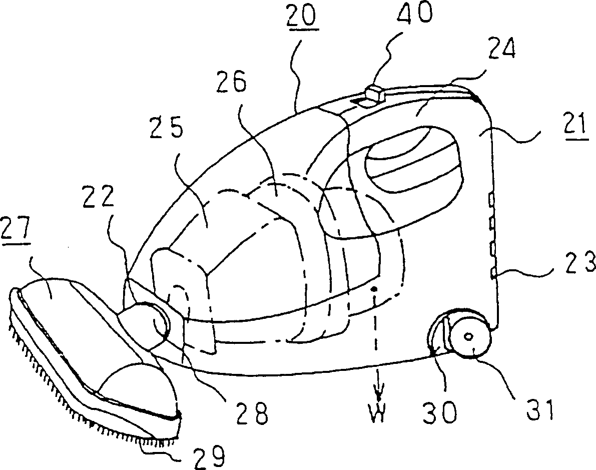
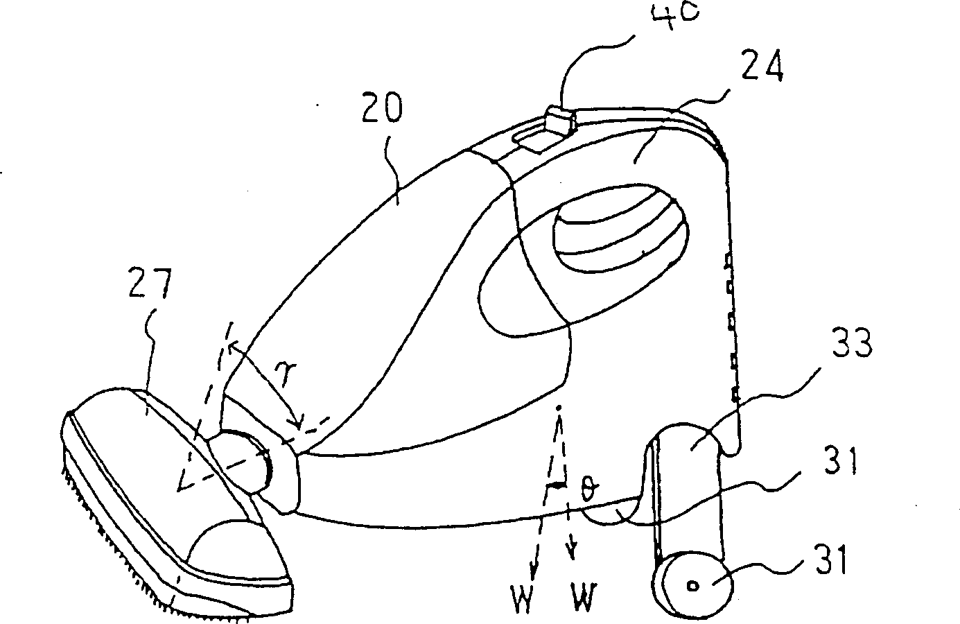
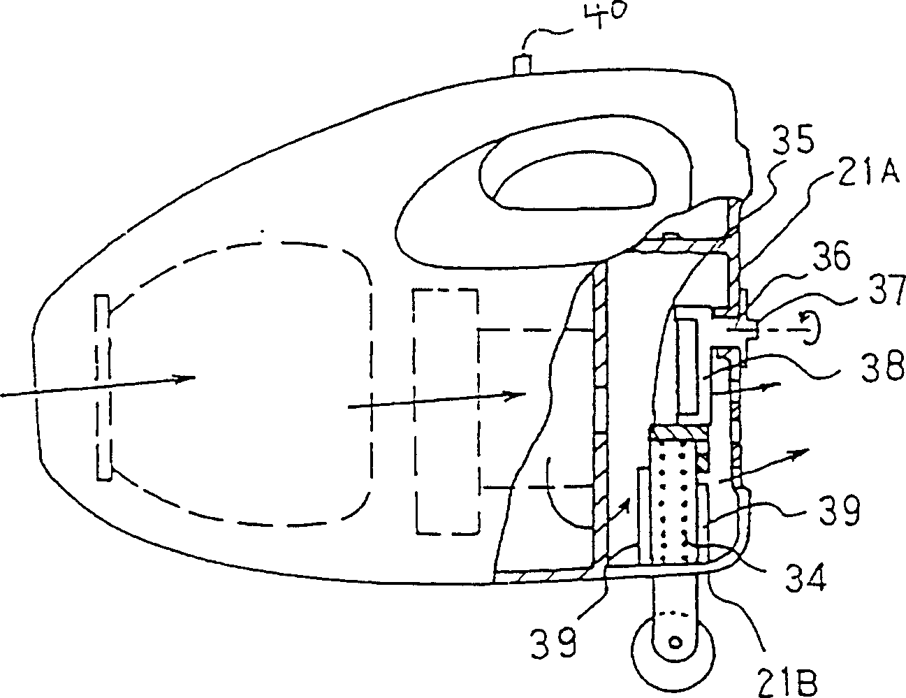
[0025] Refer below Figure 1 to Figure 6 The first embodiment of the present invention will be described. figure 1 It is a perspective view showing the whole of the small electric vacuum cleaner of the first embodiment, figure 2 A perspective view showing the state of use with the wheels extended, image 3 is a partial cross-sectional view, Figure 4 It is an enlarged view of the main part at the time of wheel storage, Figure 5 is a perspective view of the wheel support part, Figure 6 It is a perspective view of a rotary operating body. In the figure, arrows indicate the flow of air.

[0026] In the figure, 20 is a small electric vacuum cleaner, 21 is the main body of the vacuum cleaner, a suction port 22 is formed at the front part, an exhaust port 23 is formed at the rear part, and a handle 24 is formed at the upper rear part. 25 is formed by a paper bag, a cloth bag, etc. Dust collecting body, 26 is electric blower, and they are contained in the vacuum cleaner mai...

Embodiment 2

[0031] Figure 8 An overall perspective view showing the small electric vacuum cleaner of Embodiment 2 in use, Figure 9 It is a perspective view of the wheel support member. In the figure, the same parts as those in Embodiment 1 are marked with the same symbols, and their descriptions are omitted here. In the figure, 30A is the elongated wheel storage part that is formed on both sides below the cleaner main body 21, and 41 is a rotary shaft that runs through between the two wheel storage parts 30A, and it is rotatably supported in the opposite wheel storage part 30A. 33A is an arm formed at both ends of the rotary shaft 41, and the wheel 31 is attached to the front end of the arm 33A. β is the turning angle of the arm 33A.

[0032] In Example 2 with the above structure, when vacuuming the cleaning surface, the arm 33A is rotated to the rear of the cleaner main body 21, and the wheels 31 on both sides are stretched out. In this state, by holding the handle 24 and vacuuming...


PUM


Abstract

The invention provides a small vacuum cleaner which can be lightly operated by protruding a wheel from the rear of a main body of the cleaner and in which suction performance can be improved by moving the center of gravity of the main body of the cleaner toward a floor suction device so that the floor suction device makes contact surely with a floor surface to improve the performance. There are provided a vacuum cleaner body 21 into which a dust collecting body 25 and a motor-operated blower 26 are incorporated and which includes a suction port 22 at its front, an exhaust port 23 at its rear, and a handle 24 above it rear, a floor suction device 27 releasably mounted to the suction port 20, and a wheel 31 at the rear of the cleaner body 21, and the wheel 31 is formed so as to be retracted from the bottom surface of the vacuum cleaner body.

Description

technical field [0001] The invention relates to a main body of a hand-held small electric sweeper (dust collector). Background technique [0002] Figure 10 It is, for example, a side view of a conventional small-sized electric vacuum cleaner shown in Japanese Patent Application Laid-Open No. 8-228968, Figure 11 It is a side view of a conventional electric vacuum cleaner shown, for example, in JP Sho 30-5374, Figure 12 yes Figure 11 An enlarged view of the main part of . [0003] Figure 10 Among them, 1 is a small electric vacuum cleaner, 2 is the main body of the vacuum cleaner, with a suction port 3 at the front, an exhaust port 4 at the rear, and a handle 5 at the top. 6 is a dust collecting body such as a paper bag filter for dust collection, The 7th, electric blower, they are contained in the vacuum cleaner main body 2 respectively. 8 is a suction tool for the floor, which is mounted on the suction port 3 in a detachable manner. In the figure, F represents the ...

Claims


Application Information

Patent Timeline
Patent Type & Authority Patents(China)
IPC IPC(8): A47L9/00A47L5/24A47L9/28
CPCA47L5/24A47L9/009B60B33/04
Inventor 小池利男五十岚明
Owner MITSUBISHI ELECTRIC CORP
Features
  • R&D
  • Intellectual Property
  • Life Sciences
  • Materials
  • Tech Scout
  • Unparalleled Data Quality
  • Higher Quality Content
  • 60% Fewer Hallucinations
Learn More