
Gear change device

A speed change device and gear technology, applied in the field of gearboxes, can solve problems such as poor oil leakage prevention effect, achieve the effects of increasing gear life, reducing grease leakage, and improving oil leakage prevention effect

Pending Publication Date: 2019-10-22
POSITEC POWER TOOLS (SUZHOU) CO LTD
View PDF0 Cites 0 Cited by
  • Summary
  • Abstract
  • Description
  • Claims
  • Application Information

AI Technical Summary

Problems solved by technology

[0004] Based on this, it is necessary to provide an improved gear transmission device for the problem of poor oil leakage prevention effect of traditional gearboxes

Method used


Image

  • Gear change device
  • Gear change device
  • Gear change device

Examples


Embodiment Construction

[0041] In order to make the above objects, features and advantages of the present invention more comprehensible, specific implementations of the present invention will be described in detail below in conjunction with the accompanying drawings.

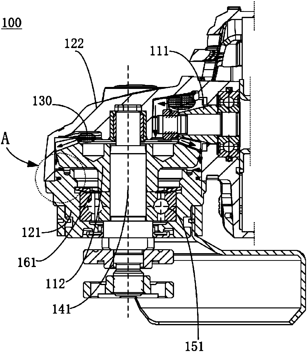
[0042] refer to figure 1 , the gear transmission device 100 includes a housing, a bearing, a bearing sealing structure, a gear shaft, gears and an oil-repelling structure.

[0043] Specifically, according to the gear transmission type design, the gear transmission device 100 may be a planetary gear reducer, or a gear-worm reducer, a planetary gear speed increaser, a gear-worm speed increaser, and the like. According to the shape and type design of the gears, the gear transmission device 100 can also be a cylindrical gear transmission, a bevel gear transmission, a bevel-cylindrical gear transmission, and the like.

[0044] The gear is mounted on the gear shaft. Gears are used to change speed. Specifically, the gears include a driving...


PUM


Abstract

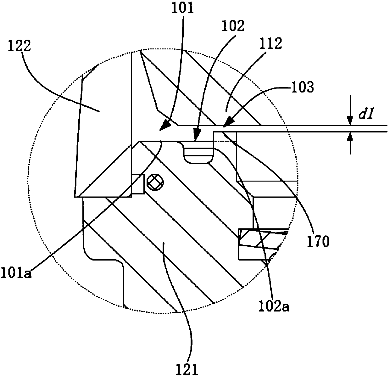
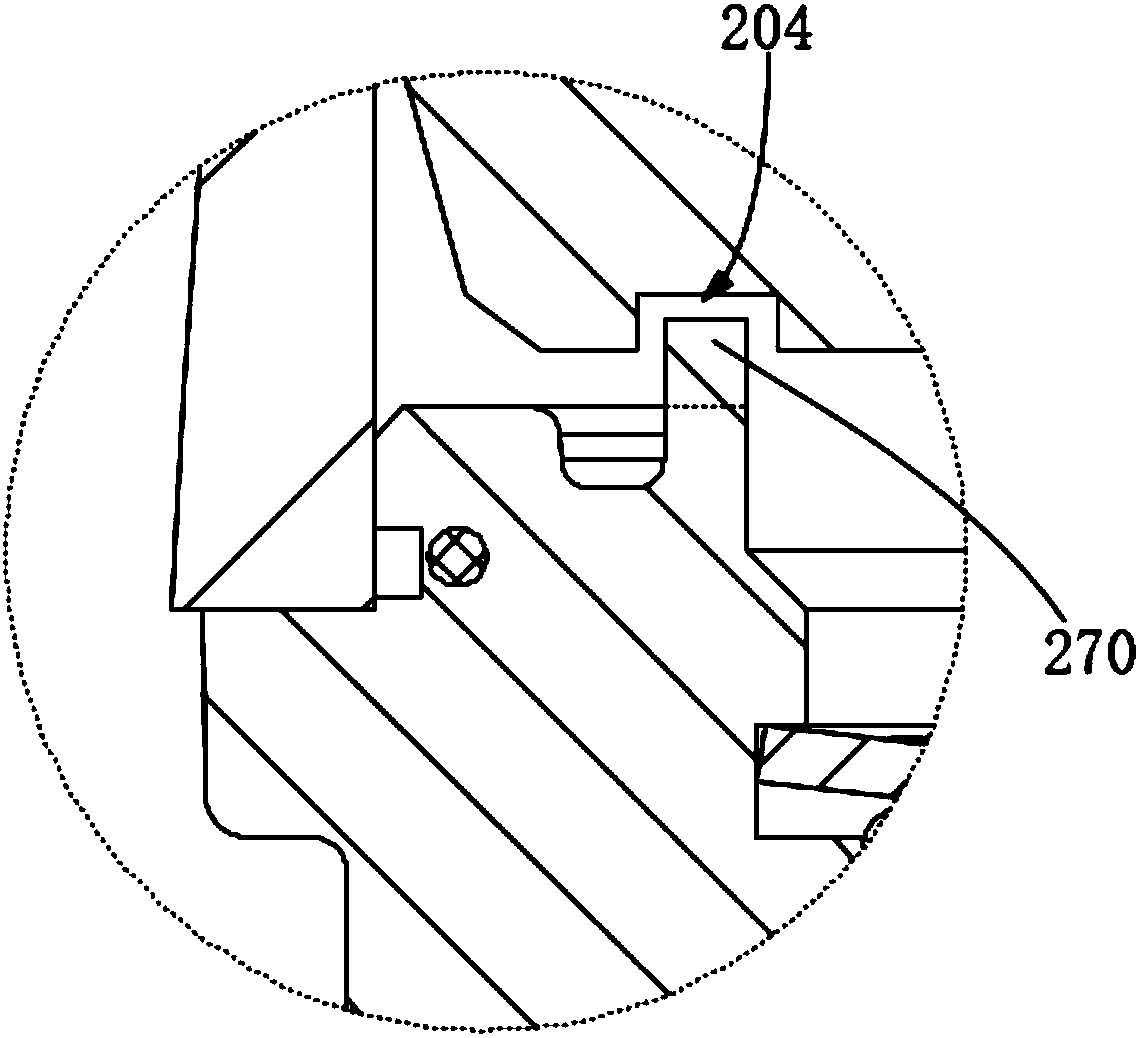
The invention relates to a gear change device. The gear change device comprises a shell, a bearing, a bearing seal structure, a gear shaft, a gear and an oil blocking structure. The bearing seal structure is used for sealing the bearing, the gear shaft is connected with the inner wall of the shell through the bearing, the gear is mounted on the gear shaft, and is located in the shell, the gear isused for speed change, and a gap is formed between the gear and the shell. The oil blocking structure is arranged on the grease flowing path in the shell and is used for blocking the grease from flowing to the bearing seal structure through the gap. When the grease in the gear change device flows along the flowing path during leaking, the oil blocking structure can block part of grease from flowing through the gap; even if a small amount of grease is not blocked by the oil blocking structure, the grease can be further blocked from leaking through the bearing seal structure, and the grease leaking prevention effect of the gear change device can be improved.

Description

technical field [0001] The invention relates to the technical field of gearboxes, in particular to a gear transmission device. Background technique [0002] Gearboxes are widely used in machines such as angle grinders, electric hammers, and polishing machines. Gearboxes usually contain a quantity of grease that is used to lubricate the gears. When the machine starts, it will generate a lot of heat, which will increase the pressure in the oil chamber and dilute the grease at the same time. A large amount of grease will flow out from the oil chamber of the gearbox until it flows through the bearing, leaks from the bearing, and leaks to the The outer surface of the machine, thereby corroding the machine. [0003] The traditional gear box only relies on the bearing sealing structure to prevent oil leakage, and the oil leakage prevention effect is poor, and it is difficult to prevent the grease of 0# and below grades and the 1# grease diluted at high temperature. Contents of ...

Claims


Application Information

Patent Timeline
Patent Type & Authority Applications(China)
IPC IPC(8): F16H57/029
CPCF16H57/029
Inventor 卞印航周中亚闵军辉
Owner POSITEC POWER TOOLS (SUZHOU) CO LTD
Learn More