Hydraulic vibration damping device and engineering machinery

A technology of hydraulic vibration reduction and hydraulic components, which is applied in the direction of fluid pressure actuation devices, mechanical equipment, supporting machines, etc., can solve problems such as functional defects, inability to target vibration reduction, restrictions, etc., and achieve the effect of optimal vibration reduction effect

Pending Publication Date: 2019-10-22
JIANGSU XCMG CONSTR MASCH RES INST LTD
View PDF1 Cites 0 Cited by
  • Summary
  • Abstract
  • Description
  • Claims
  • Application Information

AI Technical Summary

Problems solved by technology

However, the existing patents are mainly based on the deformation of the rubber part to absorb and transform its vibration and impact. It does not consider the frequency domain characteristics of the vibration of the hydraulic valve, and it cannot be targeted for vibration reduction. The effect is limited.
[0009] 3. The above-mentioned patent is composed of longitudinal vibration-damping rubber sleeves, ferrules, supports and radial vibration-damping rubber sleeves, etc., and belongs to the assembly design, which will lead to certain functional defects
For example, the effective stroke of longitudinal vibration damping of the vibration damping device depends on the deformation of the longitudinal vibration damping rubber sleeve, which will be significantly limited.

Method used


Image

  • Hydraulic vibration damping device and engineering machinery
  • Hydraulic vibration damping device and engineering machinery
  • Hydraulic vibration damping device and engineering machinery

Examples


Embodiment Construction

[0038] The present invention will be further described below in conjunction with the accompanying drawings. The following examples are only used to illustrate the technical solution of the present invention more clearly, but not to limit the protection scope of the present invention.

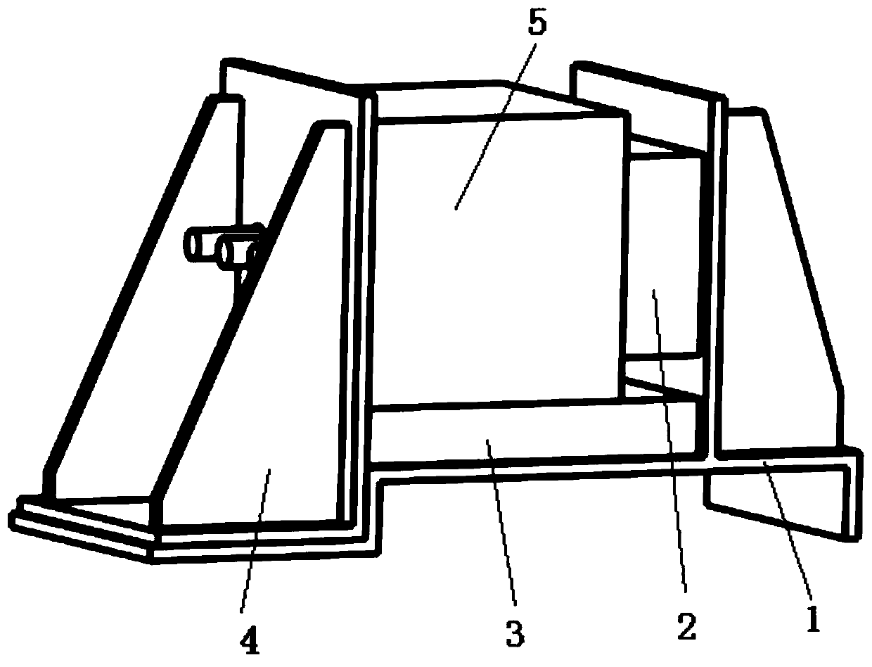
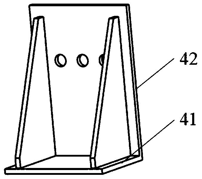
[0039] Such as figure 1 and figure 2 As shown, a vibration damping device for a hydraulic valve of the present invention includes a mounting base 1, an oil flow direction vibration damping package 2, a base vibration damping package 3, a compression bracket 4, and the like.

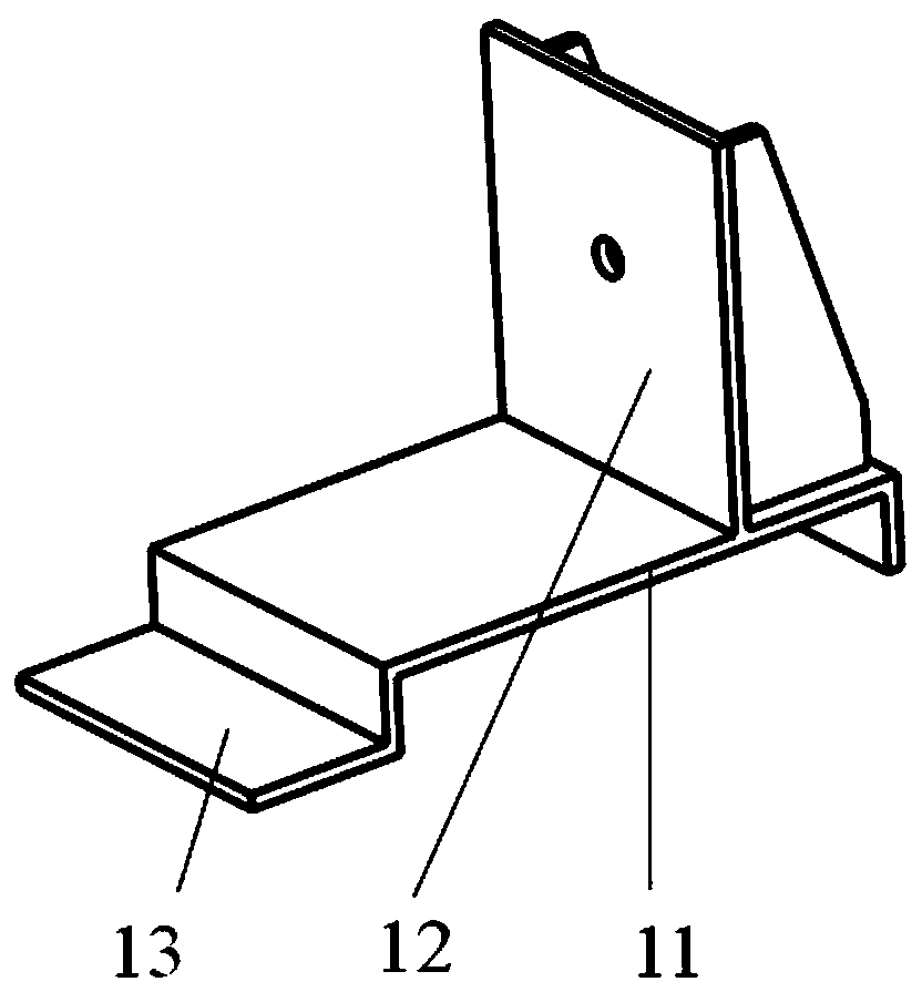
[0040] The installation base 1 includes a base surface 11, a fixed vertical surface 12 and a horizontal surface 13 for fixing the hydraulic component 5, wherein the base surface 11 and the horizontal surface 13 are horizontal and have a certain distance in height, and the fixed vertical surface 12 is vertically arranged on the oil surface. in the flow direction.

[0041] The oil flow damping package 2 is a combined stru...


PUM


Abstract

The invention discloses a hydraulic vibration damping device. The hydraulic vibration damping device comprises an oil flow direction vibration damping bag, a base vibration damping bag, a compressingsupport and a mounting base used for bearing the parts; the base vibration damping bag is arranged on the mounting base, the oil flow direction vibration damping bag is arranged above the base vibration damping bag and is arranged in the oil flow direction of a hydraulic component; and the oil flow direction vibration damping bag and the base vibration damping bag are limited on the mounting baseby the pressure applied by the compressing support along the oil flow direction of the hydraulic component. The vibration damping device of the hydraulic valve can reduce vibration in multiple directions such as hydraulic oil flow direction and base normal direction and is convenient to install; so that the vibration damping cost can be flexibly controlled according to the application environment;and the vibration frequency domain characteristics of the hydraulic valve can be designed in a targeted manner, so that the better vibration damping effect is achieved.

Description

technical field [0001] The invention relates to the field of vibration and noise of hydraulic systems, in particular to a hydraulic vibration damping device and engineering machinery. Background technique [0002] The hydraulic system is the key system of construction machinery, which can ensure that it can complete excavation, lifting and other actions. When working, the vehicle will inevitably produce strong vibrations. Hydraulic valves are important components of the hydraulic system. Under strong vibrations, the dynamic characteristics of the hydraulic valves will change, resulting in displacement of the valve core, resulting in fluctuations in its pressure and flow. It greatly affects the working stability of the vehicle operation. [0003] At present, hydraulic valves and the like are generally connected with matching valve blocks first, and then directly fixed on the base with bolts. During operation, hydraulic valves, etc. vibrate due to changes in inlet and outlet...

Claims


Application Information

Patent Timeline
IPC IPC(8): F16M5/00F16F15/023F16F15/08F15B21/00
CPCF16M5/00F16F15/022F16F15/0232F16F15/023F16F15/08F15B21/008
Inventor 倪翔宇刘帅张青元高磊磊
Owner JIANGSU XCMG CONSTR MASCH RES INST LTD
Why Eureka
Try Eureka