Multiple clutch device

a multi-claw technology, applied in the direction of yielding couplings, couplings, mechanical devices, etc., can solve the problems of increasing the axial construction space requirement of dual clutches, increasing the unsteady running of the drive units, and increasing the unsteady running of the drive units. , to achieve the effect of increasing the unsteady running of the drive units, and reducing the overall number of cylinders

Active Publication Date: 2011-12-01
SCHAEFFLER TECH AG & CO KG
View PDF5 Cites 22 Cited by
  • Summary
  • Abstract
  • Description
  • Claims
  • Application Information

AI Technical Summary

Benefits of technology

[0005]At the present time, for energy efficiency reasons, attempts are made to reduce an overall number of cylinders of internal combustion engines, in particular 2-cylinder or 3-cylinder engines being developed. However, with a reduced number of cylinders, there is an increase i

Problems solved by technology

However, with a reduced number of cylinders, there is an increase in unsteady running of the drive units.
With an increase in unsteady running of the drive units, the torsion

Method used


Image

  • Multiple clutch device
  • Multiple clutch device
  • Multiple clutch device

Examples


Embodiment Construction

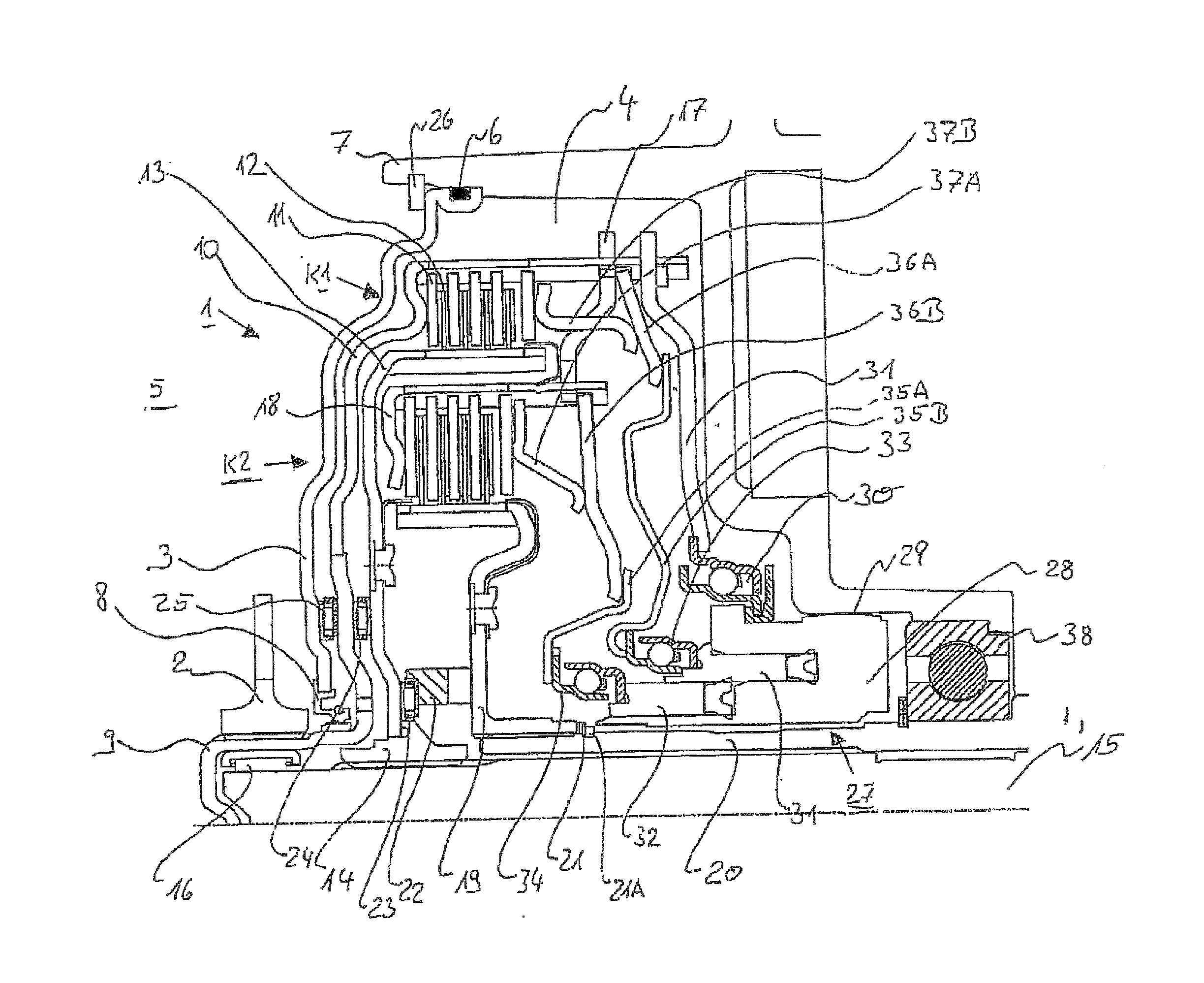
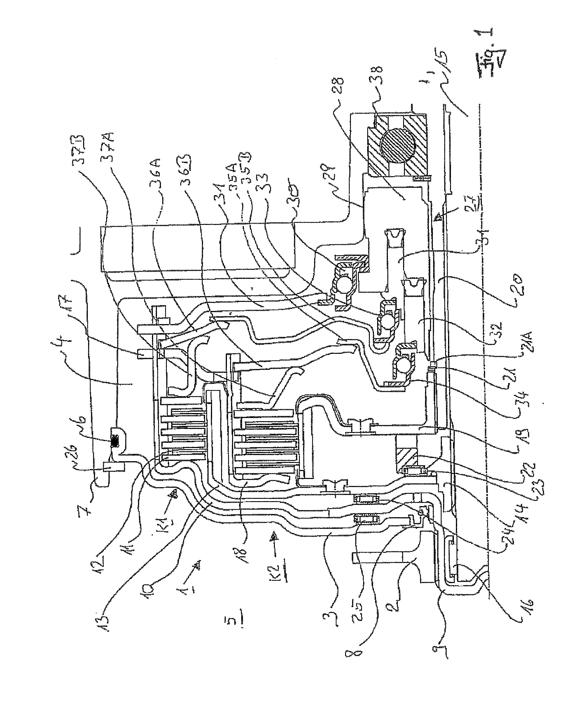
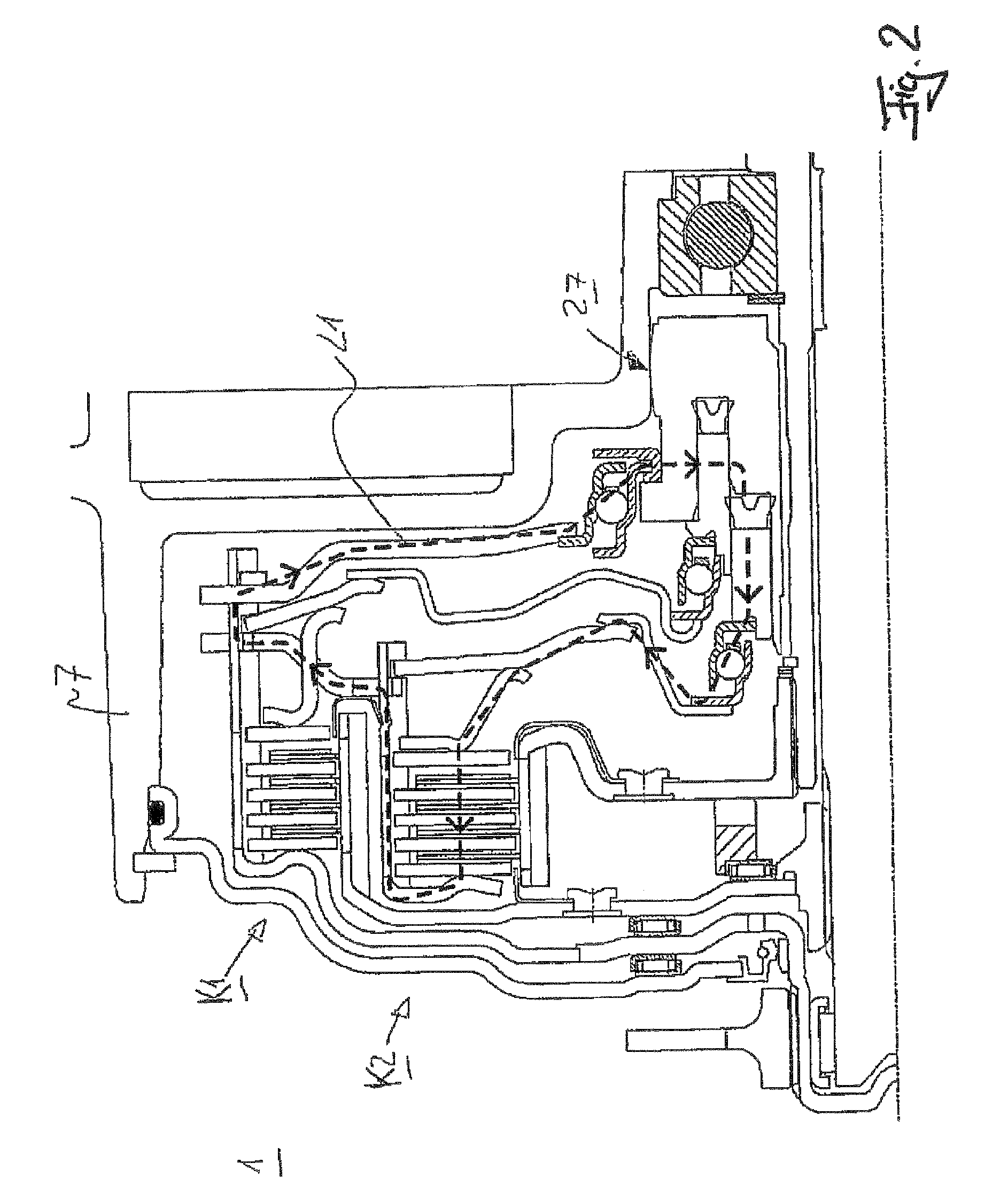
[0027]FIG. 1 shows a dual clutch 1 composed of two radially nested wet-running multi-plate clutches K1 and K2. Clutch K1 is in this case arranged radially on the outside and clutch K2 radially on the inside. The dual clutch 1 is driven by an output hub 2 of a two-mass flywheel (not shown in detail) preceding the clutch 1.

[0028]Between this two-mass flywheel and the dual clutch 1 is located a clutch cover 3 which separates a wet space 4 from a dry space 5. Static sealing 6 of the clutch cover 3 with respect to a transmission housing 7 of a transmission (not shown in detail) following in the drive train takes place preferably via an O-ring 6 or another static sealing element.

[0029]Sealing with respect to the dual clutch 1 takes place preferably via a radial shaft sealing ring 8 as a dynamic sealing element.

[0030]The output hub 2 of the two-mass flywheel (also designated below briefly as ZMS) is connected fixedly in terms of rotation to a clutch hub 9 via a toothing. The clutch hub 9 i...


PUM


Abstract

A multiple clutch device which includes a drive unit, a downstream transmission connected to a drive shaft of the drive unit and accommodated in a clutch bell that does not co-rotate with the drive shaft, two wet multi-plate clutches, which include a plate support at the input and output end and plates alternating axially, and an actuation mechanism. A housing of the actuation mechanism is supported on the clutch bell, and the plate support at the input end of at least one of the multi-plate clutches is connected to the housing by a supporting metal sheet or a supporting pot and a footstep bearing such that a flow of an actuation force generated by the actuation mechanism is redirected to the housing of the actuation mechanism via the supporting metal sheet or the supporting pot and the footstep bearing, creating a closed force flow within the device.

Description

[0001]This application is a continuation of PCT / DE2009 / 001809 filed Dec. 22, 2009, which in turn claims the priority of DE 10 2009 005 075.2 filed Jan. 19, 2009, and DE 10 2009 012 207.9 filed Mar. 9, 2009. The priority of these applications is hereby claimed and these application are incorporated by reference herein.FIELD OF THE INVENTION[0002]The present invention relates to a multiple clutch device for a drive train with a drive unit and with a following transmission, which device is connected to a drive shaft of the drive unit and is received in a bell-shaped clutch casing not corotating with the drive shaft of the drive unit, with two multi-plate clutches which have in each case an input-side and output-side plate carrier and plates alternating in the axial direction, and with an actuating device.BACKGROUND OF THE INVENTION[0003]A dual clutch device of this type is known from DE 10 2006 049 731. In this dual clutch, an actuating force generated by the actuating device has to be...

Claims


Application Information

Patent Timeline
IPC IPC(8): F16D21/00
CPCF16D3/66F16D21/06F16D2300/26F16D25/10F16D2021/0661F16D25/0638F16D25/087
Inventor ARNOLD, JOHANNESNOEHL, OLIVERAGNER, IVO
Owner SCHAEFFLER TECH AG & CO KG
Why Eureka
Try Eureka